Introduction
Jaycar in Australia have a range of Arduino compatible kit, one such piece is the Duinotech 8 x 8 LED Dot Matrix Module Red. They provide the following specifications:
A 64 Red LED matrix, this module is easily controlled with the Led Control library. Display your own custom characters, or use multiple modules together to make a scrolling display.
• Operating Voltage: 5VDC
• Protocol: SPI (Shift-Register)
• Chipset: MAX7219
• LED Colour: RED
• Dimensions: 62(W) x 32(H) x 14(D)mm
This is fine but doesn't really demonstrate how to use it. So I don't have figure this out again and to hopefully assist someone else who might want to use the module, I have summarised the key information below.
Hardware
Connection is very straight forward. From the dot matrix module:
VCC - connects to 5V on the Arduino
GND - connects to GND
CLK - connects to Arduino D10
CS - connects to Arduino D11
DIN - connects to Arduino D12
You can change the CLK, CS and DIN pin assignments in the software (see below).
Software
To drive this module you need the LedControl library. LedControl is an Arduino library for MAX7219 and MAX7221 Led display drivers. The code also works with the Teensy. Download this library and unzip it into your Arduino libraries folder. You can then try out the library using the sample code provided.
#include <LedControl.h>

int DIN = 12;
int CS =  11;
int CLK = 10;

LedControl lc=LedControl(DIN,CLK,CS,0);

void setup(){
 lc.shutdown(0,false); // The MAX72XX is in power-saving mode on startup
 lc.setIntensity(0,7); // Set the brightness, 15 = maximum value
 lc.clearDisplay(0);   // and clear the display
}

void loop(){

    byte smile[8]=   {0x3C,0x42,0xA5,0x81,0xA5,0x99,0x42,0x3C};
    byte neutral[8]= {0x3C,0x42,0xA5,0x81,0xBD,0x81,0x42,0x3C};
    byte frown[8]=   {0x3C,0x42,0xA5,0x81,0x99,0xA5,0x42,0x3C};

    printByte(smile);
    delay(1000);
    printByte(neutral);
    delay(1000);
    printByte(frown);
    delay(1000);
    lc.clearDisplay(0);
    delay(1000);
}

void printByte(byte character [])
{
  int i = 0;
  for(i=0;i<8;i++)
  {
    lc.setRow(0,i,character[i]);
  }
}
The initialization code for the lc variable through which we talk to the MAX72XX devices takes 4 arguments. The first 3 arguments are the pin-numbers on the Arduino that are connected to the MAX72XX. These can be any of the digital IO-pins on an Arduino. In the example, pins 12,11 and 10 were chosen.
The fourth argument to LedControl(dataPin,clockPin,csPin,numDevices) declaration is the number of cascaded MAX72XX devices that you're using with this LedControl. The library can address up to 8 devices from a single LedControl variable. There is a small performance penalty with each device you add to the chain, but the amount of memory used by the library code will stay the same, no matter how many devices you set. Since one LedControl cannot address more than 8 devices, only values between 1-8 are allowed.
The fourth argument to LedControl(dataPin,clockPin,csPin,numDevices) declaration is the number of cascaded MAX72XX devices that you're using with this LedControl. The library can address up to 8 devices from a single LedControl variable. There is a small performance penalty with each device you add to the chain, but the amount of memory used by the library code will stay the same, no matter how many devices you set. Since one LedControl cannot address more than 8 devices, only values between 1-8 are allowed.
LED Byte Generator
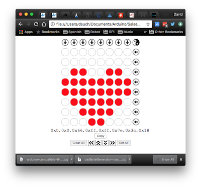
If you want to design your own images to display on the Dot Matrix module, the easiest way is to download the LED Byte Generator written by Bernhard Hofmann. This Javascript app generates byte codes for sending to an LED matrix.
It works for for 8x8 LED matrices driven by the MAX7219/MAX7221 to use in code such as C/C++ or Energia and run on an Arduino, Raspberry Pi or micro controller such as the MSP430.
To run the app, just File - Open the index.html file in your browser.
It works for for 8x8 LED matrices driven by the MAX7219/MAX7221 to use in code such as C/C++ or Energia and run on an Arduino, Raspberry Pi or micro controller such as the MSP430.
To run the app, just File - Open the index.html file in your browser.


No comments:
Post a Comment