
Bullet Connectors

My ESC's and motor wires didn't come with bullet connectors and you could just solder these wires together but if the motor is running the wrong way then swapping the wires becomes a lot harder. Bullet connectors also make it easier to dismantle the drone in the future or replace individual components.

It may help to pre-tin the leads and make sure that you have removed enough insulation so that you can fit the wire, soldering iron and solder in the back of the plug and socket. Make sure that you place the heat-shrink on the wire before you solder it to the plug or socket. I used a different colour of heat-shrink on each wire to make it easier to track what is plugged into what.
You need four hands to solder these things so I jury rigged a bullet plug holder using pliers and an elastic band.

You may find it easier to solder the bullet plug socket to the ESC's before you solder them to the power distribution board, but it doesn't make much difference.
Once you have done the ESC's you can move onto the motors.

Make sure that the motor leads are all the way into the bullet plugs and don't move anything while the solder hardens otherwise you could get a dry (high resistance) joint.

Lessons Learned
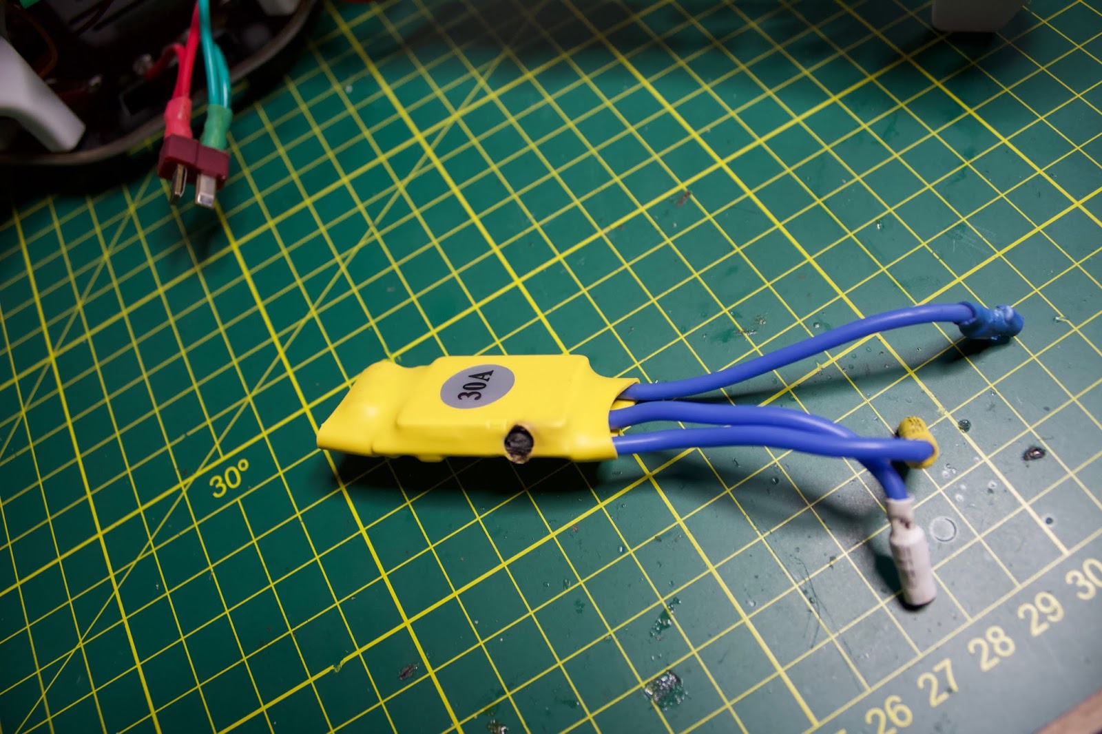
One thing that I would do different if I did this again, is to measure the length of wire required to fit neatly along the F450 frame arm and have just long enough to connect to the motor wires. I ended up leaving these wires too long which is not a problem functionally but it doesn't look as neat as it could. See the picture below.

Trim the ESC (blue) wires before attaching the bullet plugs or you will end up with this.
Also as I ended up replacing a couple of the ESC's, it would have been easier if I also had bullet connectors used for the connection to the Power Distribution Board rather than soldering them directly.
One of the burnt out ESC's.
Mount Motors on the Arms
We can now start the arm assembly. My motors come with a mounting bracket with holes that don't match up with the holes in the motor, and four very short screws. Luckily we don't need these. Use 4 of the long hex bolts which come with the F450 air frame.

Once again it feels like you need four hands but if you hold the motor and arm in place with one hand you can screw in the bolt using an appropriately sized allen key with the other. Get the first bolt just in then start on the bolt diagonally opposite. Then start the final two bolts.

Screw in each bolt only a little and then progressively tighten each bolt (similar to changing a tyre on a car). Eventually we will put loctite on these but for now just screw them in firmly (not too tight). Push the 3 motor wires through the gaps in the airframe arms. The ESC's are mounted on the underside of the arms.

You can now push the propeller holder onto the motor shaft. My motors came with collet prop adapters. This is probably one of the most common prop adapter you see people using. It has a collet that grabs the smooth motor shaft when the propeller nut and washer is tightened down.
Connect Arms to the Power Distribution Board
Traditionally the two red arms are mounted at the front of the drone, so that you can tell which direction it is pointed.

Use the small hex bolts that came with the F450 air frame to mount each of the arms to the power distribution board. You will need a smaller size allen key for these bolts.

The easiest way is to turn the power distribution board over and connect the arms from below. Make sure that the power and servo leads from the ESC's pass through the gap in the legs and don't get crushed as you attach each arm.

After mounting the arms, plug the ESC wires into the motor wires using the banana plugs. Which wires plug into which doesn't matter at this stage.

We eventually want to add up with the situation shown in the table below, so I wired arms which were diagonally opposite the same.
| Arduino | Location | Direction of rotation |
| D4 | right front | counter clockwise |
| D5 | right rear | clockwise |
| D6 | left rear | counter clockwise |
| D7 | left front | clockwise |
Finally, cable tie the ESC's to the drone arms. Try and place each ESC in a similar position on the arms to keep the drone balanced.

Attach the Top Board to the Arms
Turn the Power Distribution Board and arms over and mount the top Arduino Board using the same small hex bolts. Four are required for each arm, but the top board will block some of these holes, just use the ones you can access at this stage. Once again screw them in firmly but not too tight. We will need to pull this apart again to mount the battery, etc.


This concludes the hardware build of the drone. In part 4 we will wire up the rest of the electronics to the Arduino.


No comments:
Post a Comment