
Introduction
My interests include robotics and drones. These inevitably involve using servos and ESC's (Electronic Speed Controllers) which I would like to be able to test before I attach the Flight Controller or microprocessor which is running the show. Hence my interest in developing an ESC/Servo Tester.

Figure 1. HJ Servo Tester
You can buy ESC/Servo Testers (e.g. Figure 1) but they are pretty basic with most only supplying PWM to drive your ESC or Servo. The HJ Servo Consistency Tester shown above allows you to change the PWM pulse width (800 ~ 2200 µs @ 50 Hz) and for digital servos, the frequency [50 Hz (20 ms), 125 Hz (8 ms) or 250 Hz (4 ms)]. Note that pulse width is determined by the product of the duty cycle and frequency (freq = 1 / period).
The connections to the HJ tester are not particularly obvious. The left hand column is for power (S at top if required, 5V and GND) and then the next 4 columns are for the servo or ESC following the same order (signal, 5V and GND at the bottom).

Figure 2. HJ Connected to Saleae Protocol Analyser
I connected the HJ Tester to my Saleae Protocol Analyser, with the pulse width set to 800 µs. The results are shown in Figures 2 and 3. Our measurements show that the HJ Tester is pretty accurate, pulse width is 0.7991 ms and the frequency is 50.09 Hz.

Figure 3. Single pulse for HJ Tester at 800 µs
The select button toggles between three test modes:
- Manual - pulse width is changed by the potentiometer on the right from 800 to 2200 µs
- Centre - pulse width set to 1.5 ms (i.e. servo centred)
- Sweep - pulse width sweeps automatically from 800 to 2200 µs. The potentiometer adjusts sweep speed in this mode.
The pulse width button toggles between the three frequencies 50 Hz, 125 Hz and 250 Hz.
This functionality is ok but for ESC's in particular, most of these are now controlled with some fancy digital protocol, and it would be nice to test them using this. In addition to the different varieties of PWM, ESC's can use oneshot, multishot and Dshot protocols (amongst others). The aim is to develop a Servo/ESC tester with these protocols available. In Part 1 we will put together our own version of the HJ Tester, then in subsequent parts we will add some common digital ESC protocols.
The Arduino MegaBox
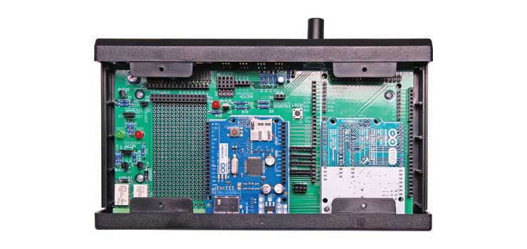
Figure 4. Altronics MegaBox for Arduino
As I happen to have an Altronics MegaBox (Figure 4) available, I will use this for my initial prototype. It has most of what I need including a LCD, 4 switches and a rotary encoder. There is an Arduino Mega 2560 clone plugged into this box to provide the smarts. The encoder will be used to select modes and adjust the PWM duty cycle / motor speed.
Servo Tester Specification
We will start off with the code for a servo tester as this is the most straight forward. Most servos will move a set number of degrees based on the pulse width of the signal on the control line. Our test servo will be the common SG90.

Figure 5. SG90 Servo
The Jaycar SG90 Data Sheet only helps with the wiring details. We need the pulse width's required to drive the servo. We found a more useful Data Sheet at MicoPik. From this we can determine the following characteristics:
- Weight: 9 g
- Dimension: 22.2 x 11.8 x 31 mm approx.
- Stall torque: 1.8 kgf·cm
- Operating speed: 0.1 s/60 degree
- Operating voltage: 4.8 V (~5V)
- Dead band width: 10 µs
- Temperature range: 0 ºC – 55 ºC
- Running current with 5V supply (no mechanical load) 220 ±50mA
- Stall current with 5V supply (horn locked) 650 ±80mA
- Idle current with 5V supply 6 ±10mA
The SG90 expects a frequency of 50 Hz on the control line and the position it moves to depends on the pulse width of the signal. the servo will move to:
- 0 degrees - the centre position with a 1.5 ms pulse;
- + 90 degrees with a ~2 ms pulse; and
- - 90 degrees with a ~1 ms pulse.
Whether + or - 90 degrees is left or right will depend on how you mounted the servo. There is no point changing the frequency of the control pulses, unless the servo you are testing expects something different to 50 Hz. The servo moves at a set speed (0.1 s/60 degrees for the SG90), regardless of how quickly you change the pulses.

Figure 6. SG90 Wiring Details
For this version of the code, we will use the rotary encoder to adjust the pulse width and the four buttons will funcion as follows:
Button 1 - min pulse width (default 1000 µs @ 50 Hz)
Button 2 - max pulse width (default 2000 µs @ 50 Hz)
Button 3 - start auto sweep
Button 4 - stop auto sweep and centre (1500 µs @ 50 Hz)
Servo Tester PWM Approaches
The Arduino Mega 2560 has 15 pins which can be used for PWM output. The simplest way to output PWM on these pins is to use the analogWrite(pin, dutyCycle) command. The PWM default frequency is 490 Hz for all pins, with the exception of pin 13 and 4, whose frequency is 980 Hz.
We tested this using our protocol analyser and found that a 50% duty cycle [analogWrite(11, 127)] provides PWM with a 1.016 ms pulse width and a frequency of 490 Hz.

Figure 7. Default analogWrite PWM
Another option is to use the Arduino Servo library. In this library you select a value between 0 and 180 degrees to set the position of the servo. So at 90 degrees (centred) you would expect a pulse width of 1500 µs. Figure 8 shows what we measured using the Servo libray with the servo set to 90 degrees, a 1.475 ms pulse width and a frequency of 49.96 Hz. So again pretty close to what is expected.

Figure 8. Servo Library PWM set to 90 degrees
Alternatively, you can access the Atmel registers directly for finer control, this allows you to change the type, range and frequency of the pulse width modulation (PWM). It isn't possible to change the frequency using either of the two previous methods.
Changing Pulse Width / Duty Cycle Using Registers
We will use pin D11 (ATmega2560 physical pin 24, Port B bit 5) as this will work for an UNO or MEGA and is our next free pin. To set D11 as an output we can use:
DDRB |= 1 << DDB5;
This line of code sets the 5th bit of the DDRB register to 1 and is equivalent to pinMode(11, OUTPUT). DDRB is the data direction register for Port B.
Most of the register based PWM examples available are for the ATmega328P and our version of the MEGA uses the ATmega2560, so you need to make sure that you are using the correct registers and timers for your microprocessor.
The ATmega2560 has 15 pins which can be used for PWM output. Instead of using analogWrite(), we can manipulate the Output Compare Registers (OCR) directly to adjust the duty cycle. The OCR is a 16 bit register. So for example, to get a 50% duty cycle, you set the OCR to half of the top counter value - referred to as "TOP" in the datasheet. The TOP value can be assigned to be one of the fixed values: 0xFFFF, 0x00FF, 0x01FF, or 0x03FF, or to the value stored in the OCRnA or ICRn Register. The assignment is dependent on the mode of operation (Figure 10).
In the data sheet the Output Compare Registers are labelled OCRxA, OCRxB or OCRxC (where x is the timer number 0..5). The association between OCR's and pins for the 2560 is shown in Figure 9.
Pin Register (2560) Pin Register (328P)
2 OCR3B
3 OCR3C 3 OCR2B
4 OCR4C
5 OCR3A 5 OCR0B
6 OCR4A 6 OCR0A
7 OCR4B
8 OCR4C
9 OCR2B 9 OCR1A
10 OCR2A 10 OCR1B
11 OCR1A 11 OCR2A
12 OCR1B
13 OCR0A
44 OCR5C
45 OCR5B
46 OCR5A
Figure 9. Arduino pins and associated Output Compare Register.
To adjust the PWM duty cycle, we can modify the appropriate Output Compare Register. For D11on the ATmega2560 the register is OCR1A.
OCR1A = 32767;
What happens next will be determined by the current mode of operation, which is set by a combination of the Waveform Generation mode and Compare Output mode bits. This is defined in Table 17-2 of the ATmega2560 data sheet (Figure 10).
The main PWM modes are "Fast PWM" and "Phase-correct PWM".
Assuming we haven't changed anything and we are in "Normal" mode, then TOP = 0xFFFF = 65535, and setting 0CR1A to 32767, should deliver PWM with a 50% duty cycle. Note that the data sheet states that "using the Output Compare to generate waveforms in Normal mode is not recommended, since this will occupy too much of the CPU time."
Testing this shows no PWM output. This is because you need to both enable the pin for output and set the PWM mode (i.e. set the COM bits) on that pin in order to get a result. So let's do that using Fast PWM.

Figure 10. ATmega2560 Modes of Operation
Fast PWM using Registers
In Fast PWM mode, the timer repeatedly counts from 0 to 255. The output turns on when the timer is at 0, and turns off when the timer matches the output compare register. The higher the value in the output compare register, the higher the duty cycle. To set the mode we want, we use the Timer / Counter Control Registers, TCCRnA and TCCRnB (where n = the timer number).
For D11 we need Timer 1 (this is explained in the next section). So we need to set the relevant bits in TCCR1A and TCCR1B. Note that this will effect pin D12 as well.
Figure 11. Timer 1 Counter Control Register Bits
We will use mode 5 (Fast PWM, 8 bit) which has a TOP = 0x00FF = 255. To get mode 5, we need to set the following bits within the TCCR's:
WGM10:3 = 0101
We will also set the Clock Select (CS) Bits to set the prescaler to 1. The appropriate value for this is:
CS10:2 = 001
The PWM frequency for the output can be calculated by the following equation (from the data sheet):

For our settings: fPWM = 16 Mhz / (1 * (1 + 255) = 16000000 / 256 = 62.5 kHz.
The various Clock Select modes are shown in Table 17-6 of the data sheet (Figure 12).

Figure 12. Clock Select Bit Options
The final part of the puzzle is setting the Compare Output Mode for the relevant type of PWM. We need Table 17-4 from the data sheet for this (Figure 13). We want non-inverting mode and will set:
COM1A0:1 = 01

Figure 13. Compare Output Mode for Fast PWM
The register code to achieve this is as follows.
DDRB |= 1 << DDB5;                 // Set D11 as an output pin
TCCR1A = 0;                              // Clear TCCR A & B bits
TCCR1B = 0;
TCCR1A = (1 << COM1A1) | (1 << WGM10);
TCCR1B = (1 << WGM12)  | (1 << CS10);
OCR1A = 127;                             // 50% Duty Cycle (i.e. 127/255)
Figure 14. Fast PWM using Registers
In the code above (Figure 14) you will notice that we clear the bits in the Timer / Counter Control Registers (TCCR1A and TCCR1B). This is required because if you are using the Arduino IDE, there is a hidden main function which calls setup() and loop(). More importantly from our perspective is the init() function which it calls first. The init() is defined in hardware/arduino/avr/cores/arduino/wiring.c. If you have a look at this file, you will see that amongst other things it sets up the TCCR's for Timers 0, 1 and 2. Thus unless we clear these registers we may get an unexpected result when we assign our bits.
int main(void)
{
    init();
#if defined(USBCON)
    USBDevice.attach();
#endif
    setup();
    for (;;) {
        loop();
        if (serialEventRun) serialEventRun();
    }
    return 0;
}
Figure 15. Arduino Main() Function
Measuring the results on our protocol analyser provides the expected outcome (Figure 16), 50% duty cycle, pulse width 8 µs and frequency 62.5 kHz. The pulse width is a product of the duty cycle and the frequency (as period is the inverse of frequency).

Figure 16. Fast PWM Output on D11.
Changing PWM Frequency using Registers
The ATmega328P has three timers known as Timer 0, Timer 1, and Timer 2. Timer 0 and Timer 2 are 8 bit timers, while Timer 1 is a 16 bit timer. Each timer has two output compare registers that control the PWM width for the timer's two outputs: when the timer reaches the compare register value, the corresponding output is toggled.
For comparison, the ATmega2560 has 2 x 8 bit and 4 x 16 bit timers. Although the registers and timers may change, the process of setting up PWM is similar for both the 328P and the 2560.
The difference between 8 bit and 16 bit timers is the resolution. 8 bits can represent 256 values (2^8) whereas 16 bits can represent 65536 values (2^16). The timer situation for the UNO's and MEGA's is summarised in Figure 17. These timer setups are done in the init() function mentioned earlier (Figure 15).
Timer 0:
Timer0 is a 8 bit timer.
For Arduino's, Timer0 is used for timer functions, delay(), millis() and micros().
Timer 1:
Timer1 is a 16 bit timer.
For Arduino's, the Servo library uses Timer1 in Uno's and Timer5 on Mega's.
Timer 2:
Timer2 is an 8 bit timer like Timer0.
In the Arduino work the tone() function uses Timer2.
Timer 3, Timer 4, and Timer 5:
Timers 3,4, & 5 are only available on Mega's. These timers are all 16 bit.
Figure 17. Arduino UNO and Mega Timer Summary
Each of the timers has a prescaler that generates the timer clock by dividing the system clock by a prescale factor such as 1, 8, 64, 256, or 1024. The UNO and the MEGA both have a system clock speeds of 16MHz and the timer clock frequency will be the system clock frequency divided by the prescale factor.
The ATmega328P has 6 PWM capable outputs and three timers. The relation between timers and PWM outputs is:
- Timer 0 controls Pins 5 and 6;
- Timer 1 controls Pins 9 and 10; and
- Timer 2 controls Pins 11 and 3.
Similarly for the ATmega2560:
- Timer 0 controls Pins 4 and 13;
- Timer 1 controls Pins 11 and 12;
- Timer 2 controls Pins 9 and 10;
- Timer 3 controls Pin 2, 3 and 5;
- Timer 4 controls Pin 6, 7 and 8; and
- Timer 5 controls Pin 46, 45 and 44.
As the two processors use different timers for different pins, our register code will not be the same for the UNO and MEGA. It would have been nice if they could have kept the first three timer pin allocations the same between chips. The allocation above is how we know that we need to use Timer 1 for pin D11 on the ATmega2560.
    // timers 1 and 2 are used for phase-correct hardware pwm
    // this is better for motors as it ensures an even waveform
    // note, however, that fast pwm mode can achieve a frequency of up
    // 8 MHz (with a 16 MHz clock) at 50% duty cycle
Figure 18. Comment from Arduino init()
Refering to the comment in the Arduino init() function (Figure 18) we note that phase-correct hardware pwm is better for motors (this is also mentioned in the data sheet), so lets use that. The dual-slope phase-correct operation gives a lower maximum operation frequency compared to the single-slope modes, but it is high enough for our purposes.
The default PWM mode set by init() for Timer 1 is mode 1 and we want mode 8 (PWM, Phase and Frequency Correct) - see Figure 10. In mode 8 we can adjust the PWM frequency using register ICR1. To get mode 8 we just set the WGM13 bit. We will use a non-inverting output as before so set the COM1A1 bit in TCCR1A.
For reasons that will become apparent below, we set the prescaler (N) to 8, to do this, the CS11 bit in TCCR1B needs to be set.
The trusty data sheet provides us with the frequency formula for phase and frequency correct PWM.

Where the N variable again represents the prescaler divider (1, 8, 64, 256, or 1024). For our settings, the calculation is:
fPWM = 16 MHz / (2 * 8 * ICR1) = 16000000 / (2 * 8 * 20000) = 50 Hz
From this formula, it is apparent that we can adjust the PWM frequency by adjusting the value in register ICR1. It also explains why we use a prescaler of 8. The system clock is 16 MHz and to get the PWM frequency we divide by 2N. If we make 2N = 16 then the relationship between fPWM and ICR1 (i.e. TOP) is straight forward. Rearranging the formula:
ICR1 = 1MHz / fPWM
For a fPWM of 50 Hz, ICR1 = 1,000,000 / 50 = 20,000.
DDRB |= 1 << DDB5;                 // Set D11 as an output pin
TCCR1A = 0;                              //  Clear TCCR A & B bits
TCCR1B = 0;
TCCR1A = (1 << COM1A1);                  //  Non-inverting output
TCCR1B = (1 << WGM13)  | (1 << CS11);    //  Phase & Freq correct PWM, prescaler N = 8
ICR1 = 20000;                            //  Freq = 50 Hz
OCR1A = 1500;                            //  pulse width = 1500 us;
Figure 19. Register Code Phase & Frequency Correct PWM at 50 Hz.
The results of the code in Figure 19 is shown in Figure 20. So for our tester we can adjust the pulse width using the value of register OCR1A and we can adjust the PWM frequency using ICR1A.

Figure 20. Phase & Frequency Correct PWM waveform at 50 Hz.
We implemented this functionality on the Mega and were able to select the required frequency and pulse width using the rotary encoder (Figures 21 and 22).

Figure 21. PWM 50 Hz and Pulse Width of 1755 µs

Figure 22. Measured PWM waveform (setting 1755 µs @ 50 Hz)
The code for this partial implementation is available from the Reefwing Gist repository. In Part 2 of this series we will develop a custom Arduino shield to implement the servo testing functionality. In Part 3 we will add some common ESC digital protocols (e.g. oneshot).
No comments:
Post a Comment