
The Arduino Servo/ESC Tester Series (Part 3)

Figure 1. Arduino and Tester Shield mounted in 3D printed enclosure.
In our first article in this series, we built a prototype Servo Tester using the Altronics MegaBox as our hardware platform. We followed this up with an article using a custom Arduino shield to make construction cheaper and easier.
As shown in Figure 1, we have created a 3D printed case for the shield version of our tester. You can download the STL files for the base, lid and LCD mount from Thingiverse. The LCD mounting bracket and hinges are connected using M3 bolts and nuts.
If we do another version of this shield, I would do a few things differently. These include:
- Moving the group of 15 tester pin headers away from the left hand hinge, towards the centre of the PCB.
- Moving the LCD connector towards the top of the PCB (or use a 90 degree connector) to allow the LCD mount to close like a lid.
- Move the potentiometer a bit further towards the front of the PCB.
- Break out the D13 LED onto the shield.
- Adding four mounting holes to the PCB and use this as the lid to the box.
Our previous prototypes only provided PWM output at varying frequencies (50 Hz, 125 Hz and 250 Hz). In this article we will add PWM 490 Hz and the OneShot125 protocol to our tester. This will be used for testing ESC's which utilise this protocol.
PWM 490 Hz (Fast PWM)
In standard PWM the maximum pulse width is 2 ms, so the highest theoretical frequency using this control strategy is 500 Hz. To get pulse separation, the practical upper limit is 490 Hz.
Adding this protocol is very easy. In part 1 of our series we found that the simplest way to output PWM is to use the analogWrite(pin, dutyCycle) command. The ATmega328P PWM default frequency is 490 Hz for all PWM capable pins (3, 9, 10 and 11), with the exception of pins 5 and 6, whose default frequency is 980 Hz.
We tested this using our protocol analyser and found that a 50% duty cycle [analogWrite(9, 127)] provides PWM with a 1.016 ms pulse width and a frequency of 490 Hz.
For our existing shield sketch we may as well continue to use the register method of setting PWM frequency. The formula that we derived in Part 1 gives us the value for ICR1 at a particular PWM frequency:
ICR1 = 1MHz / fPWM = 1MHz / 490 = 2040
Setting the ICR1 register to this value should give us PWM at 490 Hz. Updating the sketch accordingly, we measured the output on our protocol analyser (Figure 2). We ended up with a PWM frequency very close to 490 Hz. The updated code will be provided at the end of the article.

Figure 2. Output for PWM 490 Hz
We also tried connecting the 9G Servo to see if it would work at this frequency. It did to a certain extent but there was a LOT of jitter. The servo is expecting a nominal frequency of 50 Hz so these results are not surprising.
What is an ESC?

Figure 3. An example of an ESC.
An Electronic Speed Control or ESC is an electronic circuit that controls and regulates the speed of an electric motor. ESC's come in many different packages, one version is shown in Figure 2.
ESC's contain a microcontroller which take an input (e.g. direction or speed from a flight controller) and convert this to the appropriate motor control output. The flight controller (or ESC tester in our case), communicates with the ESC using an ESC protocol. The available protocols depend on the ESC firmware being used. Some examples of ESC firmware are:
- BLHeli ESC.
- BLHeli_S ESC.
- SimonK ESC.
- Kiss.
- BLHeli_32.
The ESC in Figure 3 is encapsulated in yellow heatshrink. The 3 x blue leads with bullet connectors, go to the brushless motor that is being controlled. With brushless motors, the speed of the motor is varied by adjusting the timing of pulses of current delivered to the windings of the motor. The ESC effectively creates three-phase AC power to deliver these pulses.

Figure 4. Example ESC control wiring.
In Figure 3, the thick red and black wires (ending in a male Deans T-plug) connect to the LiPo batteries and the 3 smaller wires (white, black and red) are for the ESC control (white) and to provide a regulated 5 VDC (red and black). Not all ESC's provide this regulated 5 VDC (also called a Battery Eliminator Circuit or BEC).
An example of how an ESC is used in a quadcopter design is shown in Figure 4. This design uses a quad ESC (i.e. four ESC's mounted on one PCB), controlled by a Beaglebone Blue flight controller.
The idea is that our ESC tester can be used in place of the flight controller, to allow us to test each part of the system separately.
What is OneShot?
The OneShot125 protocol consists of:
- A single pulse (hence the name OneShot) with the new response required (this is different to PWM which is a stream of pulses);
- Pulse width is between 125 µs (stop) and 250 µs (full power). This is where the 125 in the name comes from.
- Oneshot125 (pulse width 125-250 μs, maximum frequency 4 kHz);
- Oneshot42 (pulse width 42-84 μs, maximum frequency 11.9 kHz); and
- Multishot (pulse width 5-25 μs, maximum frequency 40 kHz).
OneShot125 was created by Flyduino and is supported by flight controllers which use Cleanflight, Betaflight, Raceflight and Kiss. From an ESC perspective you will need SimonK, BLHeli rev13, or KISS firmware.
OneShot42 was also developed by Flyduino as part of their KISS FC and ESC program. It is not widely supported at the moment.
Out of the three varities in the OneShot stable, Multishot is the fastest ESC protocol. To take advantage of this it requires a fast flight controller and ESC processor. It was developed by RaceFlight and again is not widely supported.
The Raceflight firmware and Multishot protocol were introduced by RS2K (RCGroups user). Raceflight is a fork (or branch) of Betaflight, meaning it used the original Betaflight code and was modified for the purpose of F4 flight controller targets.
How about DShot?
Compared to the protocols already considered, DShot is the only one which is truly digital. You could argue that PWM and OneShot are also digital since they use pulses with encoded data but the point is moot. A comparison of the theoretical data rates for OneShot and Dshot are shown in Figure 5. The advantage of DShot over OneShot is not so much about speed but reliability and flexibility. Moving to a fully digital protocol allows the introduction of error correction and bi-directional data flow.

Figure 5. DShot vs OneShot
A DShot digital message consists of 16 bits in three parts, throttle value (11 bits), telemetry request (1 bit) and the CRC checksum (4 bits). The telemetry request asks for data back from the ESC on models that support it. Transmission of telemetry data is done on a different wire. Any ESC that comes with BLHeli_S firmware should support DShot.
There are four types of DShot, differentiated by their speed of connection:
- DShot150 – 150 kbits per second or 9375 Hz update frequency
- DShot300 – 300 kbits per second or 18.75 kHz update frequency
- DShot600 – 600 kbits per second or 37.5 kHz update frequency
- DShot1200 – 1,200 kbits per second or 75 kHz update frequency
We will look at developing DShot capability for our ESC Tester in a subsequent article.
Is OneShot125 better than standard PWM?
In our original article in this series, we talked about how PWM is used to control a servo. TLDR - a 1 ms pulse width equates to stop and a 2 ms pulse width = full power. As mentioned above, the theoretical fastest refresh rate is 1 / 2ms = 500 Hz. In practice it is more like 490 Hz as you need some gap between the pulses. A consequence of this is that there is no point your flight controller running faster than 490 Hz since we can only update the motor control at this rate.
By reducing the pulse width band to 125 - 250 µs, OneShot125 is theoretically eight times faster than PWM 490 Hz. A consequence of this faster update speed is no jitter in your controls. Jitter is caused when your flight model updates quicker than your ESC can respond. With OneShot125, your flight controllers PID loop can update eight times faster than Fast PWM.
A comparison of Fast PWM and OneShot is shown in Figure 6.

Figure 6. Fast PWM vs OneShot
Programming OneShot125 for the Arduino UNO
Using our approach to date we would send continuous OneShot125 pulses in the 125 - 250 µs range (see Figure 6) as we have done for the previous PWM solutions, but that is not how OneShot operates. OneShot sends one pulse when the throttle information changes.
However, we are not writing flight controller software but an ESC tester. The ESC wont care if it gets repeated pulses with the same value. So for simplicity we will produce a stream of pulse at a frequency of about 1 kHz. The pulse width will be between 125 - 250 µs, based on the potentiometer position (simulating the throttle input).
Taking this approach allows us to reuse a lot of our exisiting code. If you need a more purist solution then you can use the OneShot125 code written for the Arduino Mega which is available on the Arduino forum.
Once again, the formula that we derived in Part 1 gives us the value for ICR1 at a particular PWM frequency:
ICR1 = 1MHz / fPWM = 1MHz / 1kHz = 1000
Setting the ICR1 register to this value should give us PWM at 1 kHz. The only other changes we need to make are to the minimum and maximum pulse widths. Register OCR1A can then be set to the required pulse width between 125 and 250.
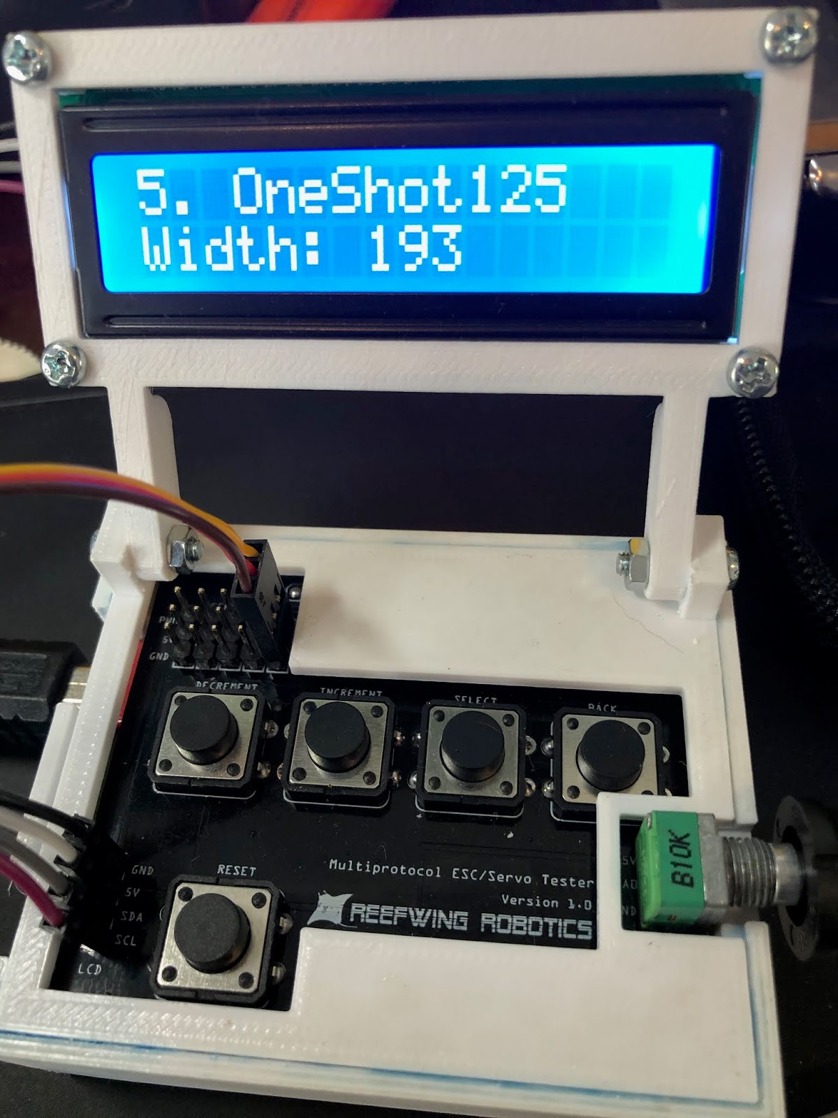
Figure 7. OneShot125 with pulse width set to 193 µs
Connecting the output of our Servo/ESC tester to our protocol analyser provides the output shown in Figures 7 and 8. As expected we get a pulse width of 193 µs at a frequency of 1kHz.

Figure 8. Output on Protocol Analyser.
Adding OneShot42 or Multishot to our ESC Tester is trivial. You just need to change the minimum and maximum pulse width values and use the same approach as that used for OneShot125. I'm not going to add it to our code because I have no need for it.
You can download a copy of the updated sketch from the Reefwing Gist.
No comments:
Post a Comment