The Arduino Servo/ESC Tester Series (Part 4)

Figure 1. Arduino & Tester Shield.
In our first article in this series, we built a prototype ESC/Servo Tester using the Altronics MegaBox as our hardware platform. We followed this up with an article using a custom Arduino shield to make construction cheaper and easier. In Part 3 we added the Fast PWM and OneShot protocols.
Synchronous vs Asynchronous Serial Protocols
Before leaping into DShot, it is useful to review other serial protocols to see how it compares.
Most serial digital communication protocols (e.g. RS232, OneWire, RS485, SPI, and I2C) require fairly precise timing in order to determine which bit is being read. We can further break down serial protocols into synchronous and asynchronous. Synchronous protocols require a separate wire for the clock signal (Figure 2) in addition to the data lines. Examples of synchronous serial communication are I2C and SPI. On the ATMega328P, SPI is the fastest synchronous communication interface allowing data transfer speeds up to half of the core clock (i.e. 8 MHz on an UNO).
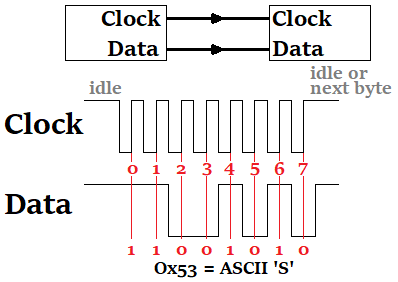
Figure 2. Synchronous Serial Data (credit)
With an asynchronous Serial Interface, the external clock signal is absent (Figure 3). This is useful when we need to transmit over longer distances. With asynchronous communication you need to know when a packet starts and stops (start bit and stop bit) and the baud rate (i.e. when to expect the next bit). Common examples of asynchronous serial protocols are RS-232, RS-422 and RS-485. Spoiler alert - DShot is an asynchronous serial protocol.

Figure 3. Asynchronous Serial Data (credit)
A Review of DShot

In case you haven't read the previous articles in our series (*gasp*), here is a quick review of the DShot ESC protocol. DShot stands for Digital Shot and is the proposed replacement for previous analogue protocols like PWM, OneShot and MultiShot. DShot was developed by Flyduino in collaboration with Betaflight.
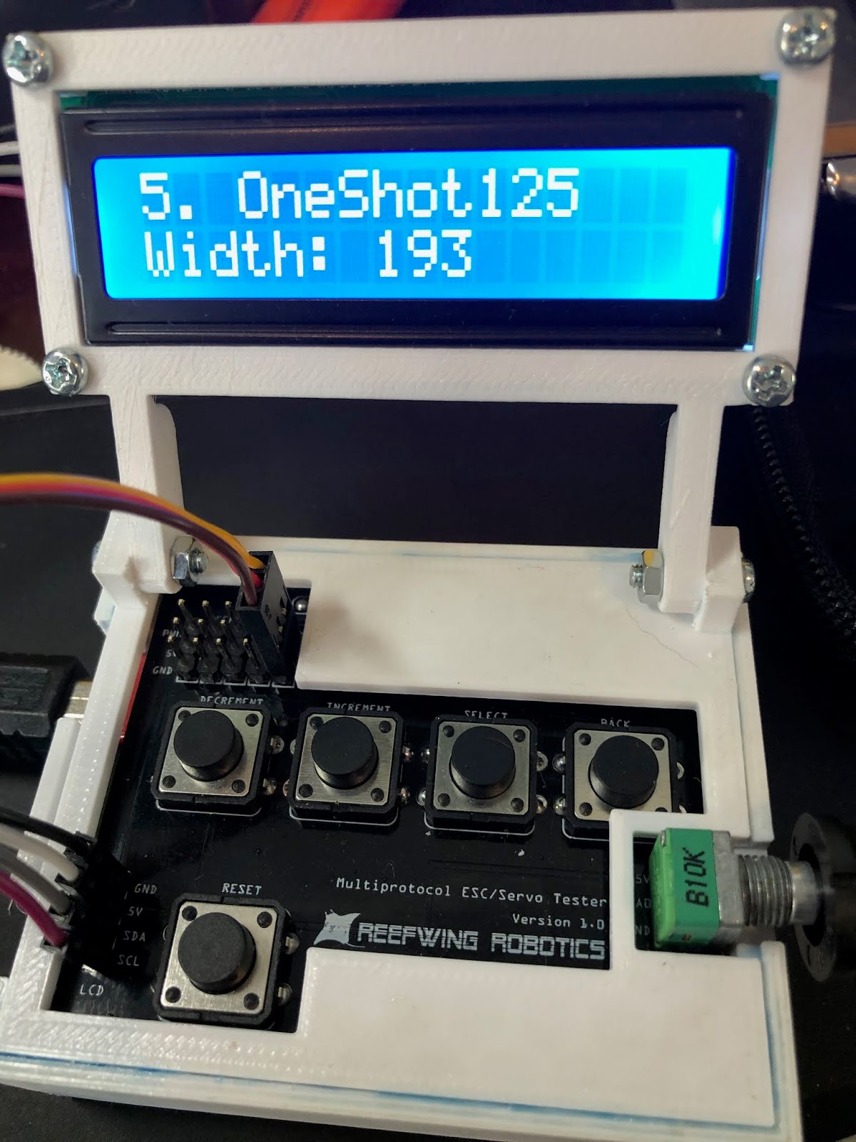
Compared to the protocols already considered, DShot is the only one which is truly digital. You could argue that PWM and OneShot are also digital since they use pulses with encoded data but the point is moot. PWM protocols, such as Multishot, Oneshot42, and Oneshot125 rely on the width of the pulse to indicate throttle position. This can introduce issues like jitter where timing variations cause errors in the desired throttle speed. The shorter the protocol pulse width the higher the likelihood and impact of jitter.
A comparison of the theoretical data rates for OneShot and DShot are shown in Figure 4. DShot is almost as fast as Multishot v1. The advantage of DShot over OneShot is not so much about speed but reliability and flexibility. Moving to a fully digital protocol allows the introduction of error correction and bi-directional data flow. In addition, with DShot no ESC calibration is required. Calibration is about tweaking the PWM pulse width which isn't required with a digital protocol. The final advantage of DShot is higher throttle value resolution (2000 steps), which should lead to smoother control.
A comparison of the theoretical data rates for OneShot and DShot are shown in Figure 4. DShot is almost as fast as Multishot v1. The advantage of DShot over OneShot is not so much about speed but reliability and flexibility. Moving to a fully digital protocol allows the introduction of error correction and bi-directional data flow. In addition, with DShot no ESC calibration is required. Calibration is about tweaking the PWM pulse width which isn't required with a digital protocol. The final advantage of DShot is higher throttle value resolution (2000 steps), which should lead to smoother control.

Figure 4. DShot vs OneShot (credit)
A DShot digital message (Figure 5) consists of 16 bits (called a frame) in three parts, throttle value (11 bits), telemetry request (1 bit) and the CRC checksum (4 bits).

Figure 6 shows a DShot message captured on an oscilloscope. Details on the three components of the DShot packet are as follows:

The 47 special reserved commands in the throttle value can be seen in the source code of betaflight:
Notes on the Special Commands (credit):
There are four types (or protocol modes) of DShot, differentiated by their speed of connection:
The maximum practical ESC update frequencies (i.e. Flight Controller loop frequencies) are substantially slower than the theoretical update rates above:

In our discussion about asynchronous serial protocols, we noted that the baud rate was critical in determining bit values. This is not as important for DShot because the bit value (1 or 0) is determined by the pulse width as a proportion of the total period. In other words, the duty cycle. Bits 1 and 0 are represented by a 74.850% and 37.425% duty cycle respectively.
As detailed in Figures 7 and 8, the signals for 0 and 1 are distinguished by their different high times, and the bit period is constant for each protocol mode. For example, with DShot600
The reason for the difference in pulse length for 0 and 1 is that it allows for some tolerance when determining the value. So these timings can be off slightly and the result will still be the same.
Unlike a number of other asynchronous serial protocols, DShot has no start or stop bit. Instead, there is normally a pause between frames of at least 2 microseconds (recommended reset time is 21 bits) to indicate a frame reset. A reset simply indicates the end of one frame and thus any future bits are the start of a new frame. With DShot occurring at the end of a Flight Controller PID loop this pause is actually considerably longer. If DShot were to be made to continuously output a signal then this delay would be required.
Any ESC that comes with BLHeli_S or KISS 24A (v1.02 or higher) firmware should support DShot.
A list of flight controllers tested to support DShot on Betaflight 3.1 is provided on the Betaflight Github repository.
Figure 5. DShot Message Format (credit)
Figure 6 shows a DShot message captured on an oscilloscope. Details on the three components of the DShot packet are as follows:
- The throttle contains 11-bit data sent from the flight controller to the ESC. It gives a resolution of 2000 throttle values. The values 0-47 are reserved for special commands (see enum code listing below), 48-2047 are for throttle control, and 0 is for disarming. In the throttle portion of the frame the most significant bits are first, consequently the bit sequence 11111111111 represents full throttle, and 10000000000 represents half throttle. In standard mode, code 48 (0b110000) is the lowest throttle setting and code 2047 (0b11111111111) is the highest throttle setting, for a full range of 2000 throttle settings.
- The telemetry bit is set if the flight controller signals a telemetry update to the ESC. The telemetry update uses a separate return wire.
- The checksum comprises a 4-bit CRC value. The checksum is calculated using CRC12, and is calculated over the throttle and telemetry request bit. The exact methodology is explained below.

Figure 6. DShot message on oscilloscope (credit)
The 47 special reserved commands in the throttle value can be seen in the source code of betaflight:
//this typedef taken from src\main\drivers\pwm_output.h in the betaflight github page
typedef enum {
    DSHOT_CMD_MOTOR_STOP = 0,
    DSHOT_CMD_BEACON1,
    DSHOT_CMD_BEACON2,
    DSHOT_CMD_BEACON3,
    DSHOT_CMD_BEACON4,
    DSHOT_CMD_BEACON5,
    DSHOT_CMD_ESC_INFO, // V2 includes settings
    DSHOT_CMD_SPIN_DIRECTION_1,
    DSHOT_CMD_SPIN_DIRECTION_2,
    DSHOT_CMD_3D_MODE_OFF,
    DSHOT_CMD_3D_MODE_ON,
    DSHOT_CMD_SETTINGS_REQUEST, // Currently not implemented
    DSHOT_CMD_SAVE_SETTINGS,
    DSHOT_CMD_SPIN_DIRECTION_NORMAL = 20,
    DSHOT_CMD_SPIN_DIRECTION_REVERSED = 21,
    DSHOT_CMD_LED0_ON, // BLHeli32 only
    DSHOT_CMD_LED1_ON, // BLHeli32 only
    DSHOT_CMD_LED2_ON, // BLHeli32 only
    DSHOT_CMD_LED3_ON, // BLHeli32 only
    DSHOT_CMD_LED0_OFF, // BLHeli32 only
    DSHOT_CMD_LED1_OFF, // BLHeli32 only
    DSHOT_CMD_LED2_OFF, // BLHeli32 only
    DSHOT_CMD_LED3_OFF, // BLHeli32 only
    DSHOT_CMD_AUDIO_STREAM_MODE_ON_OFF = 30, // KISS audio Stream mode on/Off
    DSHOT_CMD_SILENT_MODE_ON_OFF = 31, // KISS silent Mode on/Off
    DSHOT_CMD_SIGNAL_LINE_TELEMETRY_DISABLE = 32,
    DSHOT_CMD_SIGNAL_LINE_CONTINUOUS_ERPM_TELEMETRY = 33,
    DSHOT_CMD_MAX = 47
} dshotCommands_e;
Notes on the Special Commands (credit):
- If you change any settings with DShot commands, you have to issue the save settings command for them to take effect;
- To change the spin direction, set 3D mode, or save settings you must enable the telemetry bit in the associated command packet, and you must issue the command 10 times in a row for the command to take effect.
- If you issue command 0 and the ESC is not armed, it arms the ESCs with the throttle ranges set. If the ESC is armed it stops the motors. This command should be used if you want the motor to be stopped. If you try to use a throttle setting to stop the motor, it still spins slowly.
- If you stop sending commands, the ESC disarms. I haven’t timed the required update rate, but it’s pretty fast (10ms or less).
There are four types (or protocol modes) of DShot, differentiated by their speed of connection:
- DShot150 – 150 kbits per second or 9375 Hz update frequency
- DShot300 – 300 kbits per second or 18.75 kHz update frequency
- DShot600 – 600 kbits per second or 37.5 kHz update frequency
- DShot1200 – 1,200 kbits per second or 75 kHz update frequency
The maximum practical ESC update frequencies (i.e. Flight Controller loop frequencies) are substantially slower than the theoretical update rates above:
- DShot150: 4.05 kHz max
- DShot300: 8.09 - 10.6 kHz max (10.6 kHz is only available on 32 kHz gyro boards)
- DShot600: 16.0 kHz max
- DShot1200: >32.0 kHz max (Currently only KISS24 supports DSHOT1200)

Figure 7. DShot Pulse Width according to mode (credit)
In our discussion about asynchronous serial protocols, we noted that the baud rate was critical in determining bit values. This is not as important for DShot because the bit value (1 or 0) is determined by the pulse width as a proportion of the total period. In other words, the duty cycle. Bits 1 and 0 are represented by a 74.850% and 37.425% duty cycle respectively.
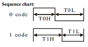
As detailed in Figures 7 and 8, the signals for 0 and 1 are distinguished by their different high times, and the bit period is constant for each protocol mode. For example, with DShot600
- Bit length (Period Time) is 1.67 microseconds = (T0H + T0L or T1H + T1L).
- For a bit to be 0, the pulse width is 625 nanoseconds (T0H – time the pulse is high for a bit value of ZERO)
- For a bit to be 1, the pulse width is 1250 nanoseconds (T1H – time the pulse is high for a bit value of ONE)
Figure 8. DShot Sequence Chart (credit)
The reason for the difference in pulse length for 0 and 1 is that it allows for some tolerance when determining the value. So these timings can be off slightly and the result will still be the same.
Unlike a number of other asynchronous serial protocols, DShot has no start or stop bit. Instead, there is normally a pause between frames of at least 2 microseconds (recommended reset time is 21 bits) to indicate a frame reset. A reset simply indicates the end of one frame and thus any future bits are the start of a new frame. With DShot occurring at the end of a Flight Controller PID loop this pause is actually considerably longer. If DShot were to be made to continuously output a signal then this delay would be required.
DShot Compatible Flight Controllers & ESC's
Any ESC that comes with BLHeli_S or KISS 24A (v1.02 or higher) firmware should support DShot.
A list of flight controllers tested to support DShot on Betaflight 3.1 is provided on the Betaflight Github repository.
Generating DShot on an Arduino UNO
Our first issue is that most flight controllers use Direct Memory Access (DMA) to generate the DShot frames. DMA allows hardware subsystems to access main system memory without using the MPU. You can think of DMA as a co-processor that is used to transfer data between main memory and peripherals without the intervention of the MPU. The advantage of this is that MPU cycles are not wasted on DShot communication and can focus on the flight controlling PID loop. A lot of the ESC's use DMA as well.
The problem is that the ATMega328P MPU does not have DMA - so neither does the Arduino UNO. The Arduino DUE has DMA but we are not using that board. There are three approaches to generating DShot on the UNO that we could find:
1. Use The UNO Hardware SPI (Serial Peripheral Interface)
Remember how the duration of the ON and OFF states in DShot are different. This is not generally how serial protocols work but you can use four SPI bytes to construct one DShot bit. This is a bit of a hack and there are a few problems with this:
- We didn't break out the SPI pins on our custom shield (doh!);
- It uses up your SPI port which may be used for something else (in theory you can have multiple devices on the SPI bus but that is probably not practical - if this is an issue then approach 2 may be the answer);
- You can only connect one ESC (not a problem for our tester but it would be if you were using the code for a quadcopter);
- Timing is a problem. As mentioned, DShot has some tolerance on pulse timing but there is at least a 250 nS pause (two clock pulses - 16 MHz clock divided by 2 for each pulse) between bytes in a SPI transmission. In practise, we measured a 0.5 μs delay between bytes (Figure 11).
- T1H = 5 μs
- T0H = 2.5 μs
- T (Period) = T1H / 74.850% = 6.68 μs
So the period of each SPI bit needs to be 6.68 / 3 = 2.23 μs (i.e a frequency 0.45 MHz). The default frequency setting for SPI is to use the system clock speed (16 MHz) divided by four, that is, one SPI clock pulse every 250 ns. You can change the SPI frequency by setting the divider to one of the following options:
- SPI_CLOCK_DIV2
- SPI_CLOCK_DIV4
- SPI_CLOCK_DIV8
- SPI_CLOCK_DIV16
- SPI_CLOCK_DIV32
- SPI_CLOCK_DIV64
- SPI_CLOCK_DIV128
The fastest rate is "divide by 2" or one SPI clock pulse every 125 ns. We need:
divider = 16 (clock speed in MHz) / 0.45 = 35.6
This doesn't really work as the closest available divider is 32. We are better of using a divider of 4 (i.e. a SPI frequency of 4 MHz) which gives us a SPI bit period of 0.25 μs. This period divides evenly into T1H and T0H. It also happens to be the default.
- T1H = 5 μs = 20 ON SPI bits
- T1L = T - T1H = 7 OFF SPI bits
- T0H = 2.5 μs = 10 ON SPI bits
- T0L = T - TOH = 17 OFF SPI bits
- T = 6.68 μs ≅ 27 SPI bits (actually 26.7, we may need to tweak this. We will need 4 SPI bytes for every DShot bit)
The other important thing for us to set is the bit data order. The DShot protocol expects MSB first. Our SPI initalisation code is thus:
SPI.beginTransaction (SPISettings (4000000, MSBFIRST, SPI_MODE0));The final parameter in the SPI initialisation is the clock mode. We are not using the clock signal or expecting a response, so it doesn't matter what you set here but for completeness, the options are:
- Mode 0 (the default) - clock is normally low (CPOL = 0), and the data is sampled on the transition from low to high (leading edge) (CPHA = 0)
- Mode 1 - clock is normally low (CPOL = 0), and the data is sampled on the transition from high to low (trailing edge) (CPHA = 1)
- Mode 2 - clock is normally high (CPOL = 1), and the data is sampled on the transition from high to low (leading edge) (CPHA = 0)
- Mode 3 - clock is normally high (CPOL = 1), and the data is sampled on the transition from low to high (trailing edge) (CPHA = 1)
To test our code and allow us to measure the results, we will repeatedly send the same DShot frame with a delay between frames. The test frame will consist of:
Throttle = 10101010101
Telemetry = 0
Checksum = 1010 (See Calculating the DShot Checksum below)
There is normally a pause between frames of at least 2 microseconds and the recommended reset time is 21 bits. We will delay for 200 μs (i.e. plenty of space between frames).
In the test sketch we are calculating the check sum every time we loop. Since the frame isn't changing we could just do this once in setup() or even hard code the check sum value, but for the ESC tester this frame will be changing and we will need to update the check sum each time that it does. By including it here we will be able to see if it creates a timing issue.
As described in the DShot SPI Test Sketch and explained above, for the Arduino UNO (16MHz CPU):
Thus there is a total of 27 SPI bits for every DShot bit. In practise we are using 32 SPI bits (4 bytes) sent 16 bits at a time.

Looking at the protocol analyser (Figure 9) we can see that this sort of works. Channel 0 on the analyser is SS (SPI Enable). This goes low at the start of transmission as expected.

It is hard to see the details in Figure 9, so we have split it up and zoomed in (Figures 10 and 11). Notice that even using the SPI.transfer16() command, there is a 0.5 μs delay between bytes as illustrated by the gap in the clock signal (channel 2 in Figure 11). Between every 16 bits there is another 1.3 μs delay. The length of a DShot "bit" is 8.7 μs. We were aiming for 6.7 μs. Most of this difference we can attribute to the delays between sending bytes.

The important thing with DShot is the duty cycle. Bits 1 and 0 should be represented by a 74.850% and 37.425% duty cycles respectively. We measured the relevant high and low bit components (Figure 12) and found:
The second LOW bit is messed up because we are seeing voltage spikes on the SS line.

At this point we gave up on the SPI approach. As we will see in Approach 3, the bit banging methodology gives a much better frame pattern, runs at DShot600 and we can use it on any digital pin, so there is no need to adjust the ESC tester hardware.
Throttle = 10101010101
Telemetry = 0
Checksum = 1010 (See Calculating the DShot Checksum below)
There is normally a pause between frames of at least 2 microseconds and the recommended reset time is 21 bits. We will delay for 200 μs (i.e. plenty of space between frames).
In the test sketch we are calculating the check sum every time we loop. Since the frame isn't changing we could just do this once in setup() or even hard code the check sum value, but for the ESC tester this frame will be changing and we will need to update the check sum each time that it does. By including it here we will be able to see if it creates a timing issue.
As described in the DShot SPI Test Sketch and explained above, for the Arduino UNO (16MHz CPU):
- DShot LOW (0) = 10 SPI bits ON, 17 SPI bits OFF = 0x07FE 0000
- DShot HIGH (1) = 20 SPI bits ON, 7 SPI bits OFF = 0x07FF FF80
Thus there is a total of 27 SPI bits for every DShot bit. In practise we are using 32 SPI bits (4 bytes) sent 16 bits at a time.

Figure 9. A DShot ON bit = 20 SPI bits ON & 7 SPI bits OFF = 0x07FF FF80
Looking at the protocol analyser (Figure 9) we can see that this sort of works. Channel 0 on the analyser is SS (SPI Enable). This goes low at the start of transmission as expected.

Figure 10. DShot ON (First 16 SPI Bits = 0x07FF)
It is hard to see the details in Figure 9, so we have split it up and zoomed in (Figures 10 and 11). Notice that even using the SPI.transfer16() command, there is a 0.5 μs delay between bytes as illustrated by the gap in the clock signal (channel 2 in Figure 11). Between every 16 bits there is another 1.3 μs delay. The length of a DShot "bit" is 8.7 μs. We were aiming for 6.7 μs. Most of this difference we can attribute to the delays between sending bytes.

Figure 11. DShot ON (Second 16 SPI Bits = 0xFF80)
The important thing with DShot is the duty cycle. Bits 1 and 0 should be represented by a 74.850% and 37.425% duty cycles respectively. We measured the relevant high and low bit components (Figure 12) and found:
- T1H = 7 μs (should be 5 μs)
- T1L = 1.7 μs (correct)
The second LOW bit is messed up because we are seeing voltage spikes on the SS line.

Figure 12. DShot T1H
At this point we gave up on the SPI approach. As we will see in Approach 3, the bit banging methodology gives a much better frame pattern, runs at DShot600 and we can use it on any digital pin, so there is no need to adjust the ESC tester hardware.
2. Additional SPI Port using USART
This is similar to Approach 1. For most Arduino devices, using the USART (Universal Serial Asynchronous Receiver Transmitter) in SPI mode is a way of generating a hardware-timed stream of bits out of one pin. This gives the UNO an additional SPI port. Unfortunately the UNO only has one serial port and it is used for programming and debugging. This option is better on the Arduino variants with more than one serial port (e.g. the Mega2560 which has four). Example code for using the USART in “Master SPI Mode” (MSPIM) is available here.
3. Bit Banging
Bit banging is slang for any method of data transmission that employs software as a substitute for dedicated hardware. In our case we are managing all the details of DShot communication, unlike SPI or USART for example which as shown in Figures 13 and 14, have dedicated hardware in the MPU to facilitate communication.

Figure 13. ATMega328P Block Diagram (credit)
Andy Tsui has written a DShot library for the Arduino, so lets compare the output of this bit banging with our SPI test.

Figure 14. SPI Hardware Block Diagram in the ATMega328P (credit)
The DShot packet produced by Andy's DShot library is shown in Figure 15. The results are so consistent that you can read the packet bits just by looking at it (1010101010101010). When using the DShot library you only pass the throttle value, the telemetry bit is fixed at 0 and the checksum is calculated within the library. This does mean that you can't use the telemetry request feature of DShot but it wouldn't be hard to tweak the library if you needed it.

Figure 15. Dshot frame produced by library
Comparing the timing of the library bits against theory we find:
- T1H = 1.3μs (Figure 16 - theoretically 1.25 μs)
- T1L = 0.3 μs (Figure 16 - theoretically 0.42 μs)
- T0H = 0.7 μs (Figure 17 - theoretically 0.625 μs)
- T0L = 1.0 μs (Figure 17 - theoretically 1.045 μs)
The results are good and there are no unwanted delays between bytes as with SPI.

Figure 16. DShot HIGH bit (T1H = W, T1L = 𝜏 - W).
If you want to produce DShot on the UNO then this library is definitely the way to go. This is the approach that we have used for our Tester.

Figure 17. DShot LOW bit (T0H = W, T0L = 𝜏 - W).
Calculating the DShot Checksum
There are LOTS of different ways that a CRC checksum can be calculated. Like just about everything else with the DShot protocol this needs to be reverse engineered. The algorithm in Figure 18 is taken from the cleanflight/betaflight source code.
This code starts with 0 and XOR's the 12 bits of our packet (11 throttle bits + 1 telemetry request bit) with that (which wont change anything since, 0 XOR 0 = 0 and 1 XOR 0 = 1). The code then right-shifts the data by four bits and XOR's the result with the value obtained in the previous step. It does this for each nibble (4 bits) in our packet (i.e. three times).
// compute checksum
int csum = 0;
int csum_data = packet;
for (int i = 0; i < 3; i++) {
 csum ^= csum_data; // xor data by nibbles
 csum_data >>= 4;
}
csum &= 0xf;
// append checksum
packet = (packet << 4) | csum;
Figure 18. Calculating the DShot (4 bit) Checksum.
The Tester Code
You can download the updated Servo/ESC Tester sketch with DShot functionality from the Reefwing Gist.
One thing to check is that the pin you want to use is on PORTD (D0-D7) for the UNO or PORTB (D8-D11) for the Leonardo. These are the default port allocations for the library. If you are connecting more than one ESC, these need to be all attached to pins on the same port.
For our tester, we are using D9 for the PWM output and this is the only pin with a header on our arduino shield. PORTB maps to Arduino UNO digital pins 8 to 13 The two high bits (6 & 7) map to the crystal pins and are not usable.
Thus in our sketch we have to define the DShot port as PORTB. We found that defining this in the sketch didn't work, so we modified the library to use Port B.
#define DSHOT_PORT PORTB
The other issue is that our PWM code is using Timer1 in a different manner to the DShot library. In other words there is a conflict. The ATMega328P has a couple of other timers. Timer 0 is used by the Arduino millis() and delay() functions, so we won't use that since we are using delay().
To address this issue we will modify the DShot library to use Timer 2. This is an 8 bit timer, whereas Timer 1 is a 16 bit timer. The DShot library is using the timer to send out packets with a frequency of 1 kHz. They used the Arduino Timer Interrupts Calculator to generate ISR code which fires 1,000 times a second (1 kHz). We can use this same site to generate code which uses Timer 2.
static void initISR(){
    // TIMER 2 for interrupt frequency 1000 Hz:
    cli(); // stop interrupts
    TCCR2A = 0; // set entire TCCR2A register to 0
    TCCR2B = 0; // same for TCCR2B
    TCNT2  = 0; // initialize counter value to 0
    // set compare match register for 1000 Hz increments
    OCR2A = 249; // = 16000000 / (64 * 1000) - 1 (must be <256)
    // turn on CTC mode
    TCCR2B |= (1 << WGM21);
    // Set CS22, CS21 and CS20 bits for 64 prescaler
    TCCR2B |= (1 << CS22) | (0 << CS21) | (0 << CS20);
    // enable timer compare interrupt
    TIMSK2 |= (1 << OCIE2A);
    sei(); // allow interrupts
}
In addition to changing the ISR initialisation code we also need to change the ISR to refer to the appropriate Timer 2 vector.
ISR(TIMER2_COMPA_vect){
   sendData();
}
To test our modifications to the DShot library we used the following sketch. The DShot data stream is on Pin D9. The output was identical to Figure 15.
#include <DShotTimer2.h>

DShot esc;

uint16_t throttle = 0b10101010101; // 0x555 or 1365 Decimal (68% throttle)

void setup() {
  esc.attach(9);
  esc.setThrottle(0);
}

void loop() {
  esc.setThrottle(throttle);
  delay(10);
}
Because we are using a common pin for DShot and PWM, we need to be able to disable DShot once we return to the home menu of the ESC Tester. To do this we detach interrupts from pin D9 and set timerActive to false. To be able to do this, we added a new public function to the DShot library called setTimerActive(bool active).
void DShot::setTimerActive(bool active){
    timerActive = active;
}
You can download a copy of the modified DShot library using Timer 2 from the Reefwing Gist. You will need 2 files:
- DShotTimer2.h; and
- DShotTimer2.cpp.
Make a copy of the original DShot Library in your Arduino libraries folder. Name the new library DShotTimer2. Replace the two files in the src directory with those you have downloaded.