Tuesday, November 7, 2017

Salae Logic & Protocol Analyzer 8 - Review and Tutorial

Overview


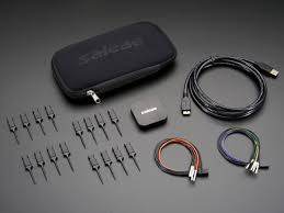
My latest acquisition is the Salae Logic Analyzer. I was very tempted to get the top of the line model, the Logic Pro 16, but decided I might as well see how useful it was before splashing out that much more cash. A reasonable compromise seemed to be the Logic 8 model.

What is a Logic / Protocol Analyzer?


A logic analyzer is an instrument that captures and displays multiple signals from a digital system or digital circuit. They are used for testing or debugging digital or logic circuits. The device
connects to a PC over USB and uses the Saleae Logic Software to record and view digital and
analog signals.  It operates by sampling a digital input connected to a device under test
(DUT) at a high sample rate. These samples are recorded to a sample buffer, and at the end of the
capture, the buffer is displayed in the software for review.

The following from the Logic 8 data sheet, explains where you would mostly use the device.

Logic analyzers are great for debugging embedded applications. In the most common case, a developer working on firmware for a microcontroller will write code to communicate with another component, possibly using protocols like serial, I2C, or SPI. To verify the functionality or
to diagnose errors in the firmware, a logic analyzer is connected to the digital IO used for
communication and records the activity during testing. The recording is then shown on the display
so the user can view the actual behavior of the firmware, and compare that with the expected
behavior to narrow down and identity the source of the issue – or verify that the operation is
correct.

Many oscilloscopes can perform a similar function, the advantage of the logic analyzer is that it can simultaneously display multiple signals (8 in my case) and relative timing information. The following from Radio Electronics, provides a good summary of the difference between a Logic Analyzer and an Oscilloscope.

  • Provide a time display of logic states:   Logic analysers possess a horizontal time axis and a vertical axis to indicate a logic high or low states. In this way a picture of the digital lines can be easily displayed.
  • Multiple channels:   Logic analyzers are designed to monitor a large number of digital lines. As logic analyzers are optimised for monitoring a large number of digital circuits, typically they may have anywhere between about 32 and 200+ channels they can monitor, each channel monitoring one digital line. However some specialised logic analyzers are suitably scaled to be able to handle many more lines, and in this way enable tracking and fault finding on much more complex systems.
  • Displays logic states:   The vertical display on the analyser displays the logic state as a high of low state. The signals enter the various channels and are converted into a high or low state for further processing within the analyser. It provides a logic timing diagram of the various lines being monitored.

Most Logic Analyzers don't allow you to analyse analogue data. The Logic 8 allows any of the 8 channels to be used for either analogue or digital analysis. The device expects an input voltage range of 0 to 5V but can handle a maximum of -25 to +25V. This is perfect for the Arduino and Raspberry Pi.

Note however  that although the device wont blow up if you connect 25V, the analog input on Logic 4 and Logic 8 is limited to +0V to +5V, and will saturate (take on minimum or maximum value) outside of this range. Logic Pro 8 and Logic Pro 16 have an analog input limited to -10V to +10V, and will saturate outside of that range. So probably not so good for working with RS 232.

Protocol Analyzers decode data that has been encoded according to a particular protocol, such as SPI or I2C. The Logic software currently offers 23 different protocol analyzers. Each protocol analyzer needs to be set up to tell it what channels to use for what (e.g. SDA = channel 0, SDC = channel 1 for I2C).

Setting Up


Getting the unit working is pretty straight forward. Start by downloading the software from Salae. Then connect the unit via the USB port. One minor irritation is that you have to connect the test clips to the wire harness yourself.


This is just a matter of pushing the lead into the test clip but it requires quite a bit of pressure or it will just fall off again. I used long nose pliers to ensure that the leads stayed put.

Bandwidth vs Sample Rate


In order to accurately record a signal, the sample rate must be sufficiently higher in order to preserve
the information in the signal, as detailed in the Nyquist–Shannon sampling theorem. Digital signals must be sampled at least four times faster than the highest frequency component in the signal.

Analog signals need to be sampled ten times faster than the fastest frequency component in the signal.

Active Channels vs Maximum Sample Rate


The maximum sample rates for digital and analog recordings is limited by the available USB bandwidth.

Because of this, sampling at the maximum rate is not possible on all channels at once. Some example sample rate combinations:

  • 3 channels, digital only, 100 MSPS
  • 2 channels, analog only, 10 MSPS
  • 8 channels, digital only, 25 MSPS
  • 8 channels, analog only, 2.5 MSPS

Using the Logic Analyzer


The big question is what can I do with this kit and is it useful? To answer this question, I will use the Logic Analyzer in a few typical scenarios and see how it goes.

Test 1 - PWM

As a first test I will look at Pulse Width Modulation (PWM) on the Arduino. Actually I will use the STEMTera breadboard for this test, it is an Arduino built into a breadboard and is handy for prototyping and testing.


I've connected an LED across pin 9 and GND, with an appropriate current limiting resistor. The simple sketch below should produce a square wave on pin 9 with a frequency of 500Hz and a 50% duty cycle.

// PWM demo to test Salae Logic 8
// 
// Arduino's PWM frequency is about 500Hz.
// A call to analogWrite() is on a scale of 0 - 255, such that analogWrite(255) 
// requests a 100% duty cycle (always on), and analogWrite(127) is a 50% duty cycle 
// (on half the time).

#define LED9    9

void setup() 
{
  pinMode(LED9, OUTPUT);
  analogWrite(LED9, 127);
}

void loop() 
{
  
}
Using channel 0 on the Logic 8 produces the following when I connect the probes across the LED.


As expected, we get a square wave with a period of 2 ms (1 / 500 Hz = 2 ms) and a 50% duty cycle. As a further check, I changed analogWrite(LED9, 64) to get a 25% duty cycle, and captured:


So for checking PWM duty cycle, this is a handy tool. The other thing that actually measuring the waveforms is good for is to test your assumptions. Initially, I was expecting the square wave to go from 0 - 5V, and if you disconnect the LED and measure from pin 9 to ground that is exactly what you get. However, with the LED in place and with our probes across the LED, the square wave goes from zero to approximately 2V. This is of course the characteristic forward voltage drop across the LED. To check this, I stuck the LED in the LCR tester which measured a Vf = 1.69V.


Test 2 - SPI

Next I will try out an application which uses the SPI protocol. This will test out the functionality of the protocol analyser and is something that you couldn't do as easily on a 2 channel DSO (since we are looking at 3 channels - DIN, CS and CLK).

We will use the Duinotech 8x8 LED Dot Matrix module described in a previous post. This communicates with an Arduino using SPI via the MAX7219 chip.

The Serial Peripheral Interface bus (SPI) is a synchronous serial communication interface specification used for short distance communication, primarily in embedded systems. The interface was developed by Motorola in the late 1980s and has become a de facto standard. Typical applications include Secure Digital cards and liquid crystal displays [Wikipedia].

The SPI bus specifies the following logic signals:

CLK: Serial Clock (output from master).
DIN: Master Output Slave Input, or Master Out Slave In (data output from master).
CS: Slave Select (often active low, output from master).
MISO: Master Input Slave Output, or Master In Slave Out (data output from slave) - not used in our application.

In our example, the Arduino is the Master and the LED Module is the Slave. As we are only connecting using 3 wires, communication is one way, from the Master to the Slave.

To begin communication, the master selects the slave device with a logic level 0 on the select line (CS). During each SPI clock cycle, a full duplex data transmission occurs. The master sends a bit on the DIN line and the slave reads it. For a 4 wire application the slave sends a bit on the MISO line at the same time and the master reads it. This sequence is maintained even when only one-directional data transfer is intended.

As described in our post on the 8x8 Led Matrix Module, we are controlling the module using the LedControl Arduino library. The first thing that we noticed when hooking up the Logic / Protocol Analyzer was that the clock speed appeared to be too slow. As expected, the CS line went low to kick things off.

The hardware SPI CLK on the Arduino is usually running at between 25kHz to 8MHz with a default of 4MHz. As shown in the screen capture below, we are measuring a clock frequency of about 64kHz.


This made me investigate the LedControl library in more detail. It turns out that the Library doesn't use the hardware SPI but emulates the SPI protocol using bit banging. In retrospect this is obvious since you can assign any digital input to the DIN, CS and CLK functions. Using hardware SPI these pins are set (see table 1).

A quick look at the LedControl source code shows that it is using the Arduino shiftOut() function to do most of the control of the logic lines. The syntax of the command is:

shiftOut(dataPin, clockPin, bitOrder, value)

It shifts out a byte of data one bit at a time. Starts from either the most (i.e. the leftmost) or least (rightmost) significant bit - MSB first for LedControl. Each bit is written in turn to a data pin, after which a clock pin is pulsed (taken high, then low) to indicate that the bit is available. So the clock speed will not necessarily be consistent, the pin transition happens when the data is ready - also not what I was expecting.

If you want to, you could trace every byte being transmitted to the LED module. For example the first byte of the "smile" image is 0x3C, you can see this being sent on the MOSI line in the screen shot below. The logic analyzer software allows you to search the decoded protocols which makes it easier to find a particular byte.


Arduino / Genuino BoardMOSIMISOSCKSS (slave)SS (master)
Uno or Duemilanove11 or ICSP-412 or ICSP-113 or ICSP-310-
Mega1280 Mega256051 or ICSP-450 or ICSP-152 or ICSP-353-
LeonardoICSP-4ICSP-1ICSP-3--
DueICSP-4ICSP-1ICSP-3-4, 10, 52
ZeroICSP-4ICSP-1ICSP-3--
10111 or ICSP-412 or ICSP-113 or ICSP-31010
MKR10008109--
Table 1. Arduino H/W SPI Pins

Conclusion


The question at the start was what can we do with a Logic / Protocol Analyser and is it useful? I have tested a couple of examples and based on this I think it will be very useful. If something is not working as expected, it may be because your assumptions were wrong. This was demonstrated very clearly above and I will be measuring my designs a lot more to ensure that the designs are doing what they should be.

Of course it also demonstrates that you don't need to understand how SPI works, to get an Arduino to talk with an 8x8 LED Module.

APPENDIX - Key Specifications - Salae Logic 8


  • Eight Digital Channels
  • 100 MSPS Digital Sampling (max)
  • 25 MHz Max Digital Bandwidth
  • Eight Analog Channels
  • 10 MSPS Analog Sampling (max)
  • 1 MHz Analog Bandwidth
  • Recording Length Limited by Available RAM and Density of Recorded Data
  • RGB LED, Customizable 24 bit Color


APPENDIX - Electrical Characteristics


Sunday, November 5, 2017

Duinotech 8 x 8 LED Dot Matrix Module Red

Introduction


Jaycar in Australia have a range of Arduino compatible kit, one such piece is the Duinotech 8 x 8 LED Dot Matrix Module Red. They provide the following specifications:

A 64 Red LED matrix, this module is easily controlled with the Led Control library. Display your own custom characters, or use multiple modules together to make a scrolling display.

•    Operating Voltage: 5VDC
•    Protocol: SPI (Shift-Register)
•    Chipset: MAX7219
•    LED Colour: RED
•    Dimensions: 62(W) x 32(H) x 14(D)mm

This is fine but doesn't really demonstrate how to use it. So I don't have figure this out again and to hopefully assist someone else who might want to use the module, I have summarised the key information below.

Hardware


Connection is very straight forward. From the dot matrix module:

VCC - connects to 5V on the Arduino
GND - connects to GND
CLK - connects to Arduino D10
CS - connects to Arduino D11
DIN - connects to Arduino D12

You can change the CLK, CS and DIN pin assignments in the software (see below).

Software


To drive this module you need the LedControl library. LedControl is an Arduino library for MAX7219 and MAX7221 Led display drivers. The code also works with the Teensy. Download this library and unzip it into your Arduino libraries folder. You can then try out the library using the sample code provided.

#include <LedControl.h>

int DIN = 12;
int CS =  11;
int CLK = 10;

LedControl lc=LedControl(DIN,CLK,CS,0);

void setup(){
 lc.shutdown(0,false); // The MAX72XX is in power-saving mode on startup
 lc.setIntensity(0,7); // Set the brightness, 15 = maximum value
 lc.clearDisplay(0);   // and clear the display
}

void loop(){ 

    byte smile[8]=   {0x3C,0x42,0xA5,0x81,0xA5,0x99,0x42,0x3C};
    byte neutral[8]= {0x3C,0x42,0xA5,0x81,0xBD,0x81,0x42,0x3C};
    byte frown[8]=   {0x3C,0x42,0xA5,0x81,0x99,0xA5,0x42,0x3C};
    
    printByte(smile);
    delay(1000);
    printByte(neutral);
    delay(1000);
    printByte(frown);    
    delay(1000);
    lc.clearDisplay(0);
    delay(1000);
}

void printByte(byte character [])
{
  int i = 0;
  for(i=0;i<8;i++)
  {
    lc.setRow(0,i,character[i]);
  }
}
The initialization code for the lc variable through which we talk to the MAX72XX devices takes 4 arguments. The first 3 arguments are the pin-numbers on the Arduino that are connected to the MAX72XX. These can be any of the digital IO-pins on an Arduino. In the example, pins 12,11 and 10 were chosen.

The fourth argument to LedControl(dataPin,clockPin,csPin,numDevices) declaration is the number of cascaded MAX72XX devices that you're using with this LedControl. The library can address up to 8 devices from a single LedControl variable. There is a small performance penalty with each device you add to the chain, but the amount of memory used by the library code will stay the same, no matter how many devices you set. Since one LedControl cannot address more than 8 devices, only values between 1-8 are allowed.

LED Byte Generator


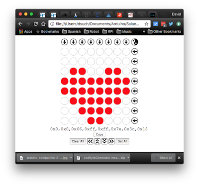
If you want to design your own images to display on the Dot Matrix module, the easiest way is to download the LED Byte Generator written by Bernhard Hofmann. This Javascript app generates byte codes for sending to an LED matrix.

It works for for 8x8 LED matrices driven by the MAX7219/MAX7221 to use in code such as C/C++ or Energia and run on an Arduino, Raspberry Pi or micro controller such as the MSP430.

To run the app, just File - Open the index.html file in your browser.


Wednesday, October 4, 2017

LCR-T4 Mega328 Component Tester


LCR-T4 Component Tester


I recently picked up an LCR-T4 Component Tester from E-Bay. I've had my eye on these for a while and for AUD12 (including the acrylic case), I thought it was worth giving one a try. There are LOTS of different versions out there.


So what does it do?

Well it measures components, including resistors (and potentiometers), inductors, capacitors, diodes, dual diodes , transistors (including MOS), SCR's, regulators, LED's, and even ESR.

Photo Credit: EEVBlog


The claimed accuracy is:

Resistance: 0.1 ohm resolution, maximum 50M ohm
Capacitor: 25pf -100,000 uf
Inductors: 0.01mh-20H

These are probably a touch optimistic but for picking out components, the accuracy is adequate.

Photo Credit: EEVBlog

This unit apparently comes with the 2013 M328 version of the software and includes a 128*64 backlit LCD display, which uses about 2mA in stand by. As you can see in the image above, the unit will automatically identify and tell you which pin is the BCE for a transistor, not to mention the gain and forward voltage - nice! One of the features is automated detection of pin assignment, which means the device can be connected to the tester in any order. You can only use pins 1,2,3 of the DIL socket.

The open source firmware and hardware design is based on the work of a couple of German dudes. If you were brave you could flash the firmware to the latest version.

Case Construction


Building the case is fairly simple. What takes the longest is peeling the paper from the laser cut acrylic sheets! Proceed as follows:

  1. Peel the paper from the acrylic (both sides).
  2. Mount the PCB on the base plate using the four smaller bolts and the spacers (see photos below). You may want to pass the battery cable under the PCB, but it isn't compulsory.
  3. Insert the side panels into the base, starting with the top one as it has the tightest fit against the screen ribbon cable.
  4. Snap the top plate in place, it will only fit one way. This should hold things in place while inserting the 4 long bolts and nuts which hold everything together. Done!


What Manual?


The first trick is to make sure that you use a fresh 9V battery, if you don't then the display will be unreadable.

Operation is pretty straight forward. Just plug the component that you want to test into pins 1, 2 or 3 on either side of the DIL socket, then press the blue test button. The unit turns itself off after displaying the results for 10 seconds. If you have surface mount components, you can use the pads on the PCB labelled 1, 2 and 3 instead of the DIL socket.

The unit will automatically detect NPN & PNP transistors, N- and P-channel MOSFETs, JFETs, diodes, small thyristors, and TRIACs. It will measure hFE and base-emitter-voltage for bipolar junction transistors (e.g. Darlingtons).

Up to two resistors can be measured with a resolution down to 0.1 ohm. The measurement range is up to 50 Mohm (Megaohm). Resistors below 10 ohms will be measured with the ESR and a resolution of 0.01 ohm. Note that resolution is not equivalent to accuracy.

Capacitors in the range 35pF (picofarad) to 100mF (millifarad) can be measured with a resolution down to 1 pF. Inductances of 0.01 mH to 20 H can be detected and measured.

The short video below shows an LED being tested.


Saturday, September 23, 2017

Raspberry Pi and Alexa Mobile Robot (Part 1)

The story so far...


In previous posts we have described building a Raspberry Pi based telepresence robot. At the moment, the robot can be remotely controlled via a web site to which it also streams video from the Pi camera. We have also added an ultrasonic sensor on a PTZ mount to allow it to roam autonomously. The next step in the robots evolution is to add voice recognition and speech using Amazon Alexa.

pi-top PULSE


The Raspberry Pi doesn't come with a microphone or speaker. There are lots of ways that you can add this capability but we decided to use the pi-top PULSE. The PULSE includes:

  • RGB LED's - 7x7 grid, illuminated speaker, underside ambient HAT and pi-top Accessory compatible;
  • SPEAKER - 2W with I2S amplifier; and a 
  • MICROPHONE - 200Hz to 11KHz response Automatic Gain Control (ACG).

Not only can we use the speaker and microphone for interfacing with Alexa but we can show some emotional/behaviour state changes via the LED's.

Wearing Multiple HATs - The 1st Problem


Even though HATs (Hardware Attached on Top) are not intended to be stacked, you can stack up to 62 HATs and not have an address collision. This assumes you don't have conflicting pin usage and you have compatible stackable headers.

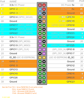
The best way to check HAT / stackable board compatibility is to map out what every pin is being used for.


The image above illustrates the pin usage for the robot. The key is as follows:

  • Orange Pins - Are general I/O pins used for the PTZ servo's and ultrasonic sensor.
  • Blue Pins - Motor Driver Board pin usage.
  • Yellow Pins - Pi Top PULSE HAT pin usage.
Thus we don't have any electrical conflicts and can move on to the mechanical interfacing issues.


To call something a HAT it must meet the HAT requirements. We are using the Seeed Motor Driver Board (shown above) which can't be called a HAT because it doesn't have a full size 40W GPIO connector or an ID EEPROM. This presents us with two problems:

  1. We need access to 6 of the 14 pins which are not extended through the Motor Board.
  2. Even if all 40 pins were extended, placing the PULSE on top of the Motor Board wouldn't allow access to the power and GPIO pins used for the servo PTZ control and ultrasonic sensor. 
To solve this issue, we need a GPIO expansion shield which provides 3 x 40 pin connections in parallel. We can then use a couple of male to female cables to connect our "HAT's". We will conclude this build in the next post (once the expansion shield has arrived).


Thursday, September 14, 2017

Flight Tracking (ADS-B) using the Raspberry Pi


In a previous post we looked at getting ADS-B tracking working on a pcDuino, to compare build difficulty with a Raspberry Pi, we built one of those as well. TL;DR version - it is much easier and you get the latest version of PiAware.

To get Dump1090 and PiAware working on a Raspberry Pi the easiest way is to just download a version of Raspbian with the software preloaded and then copy it to a SD card. Done. Full instructions are available on the FlightAware website.

We made things a bit harder for ourselves because we wanted to also try out the 4D Systems 2.4" touchscreen HAT. This requires its own drivers.

4DPi 24 HAT Display


The 4DPi-24-HAT is a 2.4" 320x240 Primary Display HAT for the Raspberry Pi, which plugs directly on top of a Raspberry Pi. It features an integrated Resistive Touch panel, enabling the 4DPi-24-HAT to function with the Raspberry Pi without the need for a mouse (theoretically). In practise the touch part of the screen is unusable. You will need a mouse to do anything useful.

Communication between the 4DPi-24-HAT and the Raspberry Pi is via the high speed 48Mhz SPI connection.

The HAT also features 5 push buttons, and a backlight. Supposedly this backlight can be configured as either On/Off or PWM controlled, selectable by an on board jumper, but only one position worked for us - see point 2 below.

The pushbuttons can be used in a python script (for example) but it isn't totally straight forward. Have a look at the data sheet for some examples.


There are a few tricks to getting this display to work with the Raspberry Pi:

  1. Make sure you download the latest drivers. The link in the instructions which came with my HAT was for an older version (which didn't work with the Raspberry Pi 3).
  2. Set the backlight link to ON/OFF not PWM. Mine came with PWM selected but it wouldn't work in this configuration. A definite trap for young players! It took me a while to track this down.
  3. You will need a couple of PCB stand offs. Get ones with a M2.5 thread and the body should be 11mm in length. These are not provided (but should be).

Optimising the Display


The 4DPi-24-HAT has a 320x240 resolution, so expectations need to be realistic about what can be usefully displayed. 

Raspbian has not been optimised to run on a display with this resolution, so there are some menus and applications which will not display correctly, or fit on the screen.

This can be helped somewhat, by setting up the display appearances, and setting fonts and
menus to be smaller. You will need to use a USB mouse and keyboard to perform this set up.

Raspberry Menu -> Preferences -> Appearance
Settings
go to Menu Bar tab
Select Small

go to System tab
click on font (Robo Light)
drag window, to see font size, select 8
(close window [x])

Click on File Manager in Menu Bar
Go to Edit, select Preferences
Select Display
Choose smallest icon sizes for all icon types
Click on "Size of Large Icons", press tab 6 times (as
the OK button is not visible), Press enter

Right click on menu bar (just left from pi menu,
near bottom edge of menu bar), to get a pop-up
menu.

Choose Add/Remove Panel Items
Remove unwanted items (eg Bluetooth)
(close window [x])

Raspberry Menu->Shutdown->Reboot

Installing Dump1090 and PiAware


To install Dump1090 and PiAware on an exisiting Raspbian installation, follow these instructions on FlightAware. It is very straight forward. The best way is to ssh in and paste the commands into terminal. Once you have plugged the USB SDR in and rebooted you should be up and running. 

We used the same USB DVB-T TV Tuner RTL2832U + R820T as our SDR. You can get these very cheaply on E-Bay.


Notice in the screen shot below that we are running the latest version of PiAware (unlike the older version we were using on the pcDuino).


Auto Load PiAware on Boot


We wanted the Raspberry Pi to auto load the PiAware web site for our ADS-B station every time the system is rebooted. To do this, first make a copy of the LXDE autostart file:

$ cp /etc/xdg/lxsession/LXDE-pi/autostart /home/pi/.config/lxsession/LXDE-pi/autostart
Then edit it:

sudo nano /home/pi/.config/lxsession/LXDE-pi/autostart
And add the following:

@xscreensaver -no-splash 
@xset s off
@xset -dpms
@xset s noblank
@chromium-browser --incognito --kiosk http://localhost:8080
Save the file, reboot and you should be good.

Comparison with pcDuino


As expected it is a lot easier (trivial in fact) to get PiAware to work on the Raspberry Pi than the pcDuino. The biggest issues we had were with the 4D Systems 2.4" Display HAT - which I don't think add much value in this instance.

Friday, August 18, 2017

Flight Tracking (ADS-B) using the pcDuino

Introduction


Interested in what planes are flying over your house? Want to know how high they are and how fast they are going? Want to build your own ADS-B ground station that can be installed anywhere and receive real-time data directly from airplanes on your computer. Then this project may be for you.

As mentioned in a previous post Diyode Magazine and Jaycar Electronics very kindly gave me a pcDuino to have a play with. Having got the 5" LCD display working with the pcDuino, I wanted to try using it as part of a project that has been on my "to do" list for some time, namely a plane tracker.

There are lots of tutorials on how to do this with a Raspberry Pi, but I think this may be the first time it has been done on the pcDuino. Everything installs pretty much as it would on the Raspberry Pi but of course the pcDuino uses an Ubuntu variant and most Pi's use Debian (or Raspbian to be precise). This means that there is a little bit more work to get things operational.


Credit to RubyDucky for providing the basis for the install technique on Ubuntu. I will note where I found differences installing on the pcDuino and the workarounds required.

ADS-B


Our plan is to track planes using ADS-B. So what is this?

ADS-B is a system in which electronic equipment onboard an aircraft automatically broadcasts the precise location of the aircraft via a digital data link. The data can be used by other aircraft and air traffic control to show the aircraft’s position and altitude on display screens without the need for radar.

The system involves an aircraft with ADS-B determining its position using GPS. A suitable transmitter then broadcasts that position at rapid intervals, along with identity, altitude, velocity and other data. Dedicated ADS-B grounds stations receive the broadcasts and relay the information to air traffic control for precise tracking of the aircraft.

Automatic – Requires no pilot input or external interrogation.

Dependant – Depends on accurate position and velocity data from the aircraft’s navigation system (eg. GPS).

Surveillance – Provides aircraft position, altitude, velocity, and other surveillance data to facilities that require the information.

Broadcast – Information is continually broadcast for monitoring by appropriately equipped ground stations or aircraft.

ADS-B data is broadcast every half-second on a 1090MHz, digital data link. The ability of a ground station to receive a signal depends on altitude, distance from the site and obstructing terrain. The maximum range of each ground station can exceed 250 nautical miles. [Credit: Air Services Australia]

Don't expect a 250 nm range with our setup. I have found the planes need to be pretty much overhead and the aerial near the window, although I do live in a valley. The signal is not designed to penetrate buildings and is pretty much line of sight. Refer to the antenna section below if you want to improve reception.

The Software Defined Radio (SDR) Receiver


The RTL2832U-based SDR receiver is designed and marketed for DVB-T reception. However, it’s possible to get raw samples from the device, rather than just a demodulated DVB signal. This means that wireless systems can then be implemented in software. I used the USB DVB-T TV Tuner RTL2832U + R820T from Wiltronics (shown above).

The RTL2832U chip is generally paired with a tuner IC and in the case of the USB receiver from Wiltronics, it’s an R820T, which enables reception from 24MHz to 1,850MHz.

Installation of the hardware is simple just plug the SDR receiver into a USB port. As there is only one USB port on the pcDuino you will probably need a hub so that you can also plug in the keyboard and mouse required for setup. I had a powered hub but it doesn't seem to need it, I think the pcDuino supplies enough current for an unpowered USB hub to work. Don't plug in the SDR receiver until instructed below.

Antenna


The antenna which comes with the USB Tuner is 100 mm in length. This works ok but is not optimised for receiving signals with a frequency of 1090 MHz. If you are having problems with reception, you could purchase the FlightAware 1090MHz antenna, or there are plenty of home brew designs online.

Software Installation


The first step is to download some packages and libraries which are required for dump1090 and piaware. Fire up the pcDuino, open LXTerminal and type the following.

$ sudo apt-get install git cmake libboost-all-dev libusb-1.0-0-dev python-scitools portaudio19-dev -y
$ sudo apt-get install tcl8.5-dev tclx8.4-dev itcl3-dev tcl-tls tcllib automake cmake telnet git gcc make

RubyDucky included tcl-tclreadline in the installation list above, but I received an "unable to locate package" error when I tried installing it. Omitting the package didn't appear to cause any subsequent issues.

RTL_SDR


RTL-SDR is a very cheap software defined radio that uses a DVB-T TV tuner dongle based on the RTL2832U chipset. Three Linux hackers found that the signal I/O data could be accessed directly, which allowed the DVB-T TV tuner to be converted into a wideband software defined radio via a new software driver. This means that a cheap TV tuner USB dongle (like the one shown above) which uses the RTL2832U chip can be used as a computer based radio scanner. This opens up all sorts of opportunities. For other project ideas have a look at the RTL-SDR website.

Download RTL-SDR (assuming you're in ~/):

$ sudo git clone git://git.osmocom.org/rtl-sdr.git

Install RTL-SDR:

$ cd rtl-sdr/
$ sudo mkdir build
$ cd build
$ sudo cmake ../
$ sudo make
$ sudo make install
$ cd ~
$ sudo cp ~/rtl-sdr/rtl-sdr.rules /etc/udev/rules.d/
$ sudo ldconfig

The kernel that comes with Ubuntu already contains a DVB driver, which we don't want to use. To stop the conflicting Linux DVB-T driver from loading, we need to blacklist it.

$ cd /etc/modprobe.d/
$ sudo nano blacklist.conf

Then add the following line at the end of the file. You can either use the existing blacklist.conf file or create a new file, as long as it is in this directory and ends in .conf.

blacklist dvb_usb_rtl28xxu

At this point you can plug in your receiver dongle and reboot. Rebooting will allow our blacklisting to take effect.

Aviation transponder interrogation modes


You may see references to s-mode when reading about ADS-B plane tracking and sometimes s-mode is used interchangeably with ADS-B (which is not strictly correct). We will take a small detour at this point to explain what this is and how it relates to ADS-B. A transponder is a piece of kit on a plane to help air traffic controllers identify a particular aircraft's position and altitude on a radar screen. This helps them maintain separation and prevent collisions. There are 3 civilian transponder modes, called A, C and S.

Mode A - Following an interrogation request, the transponder broadcasts the configured transponder code (or "squawk code").  A separate type of response called "Ident" can be initiated from the airplane by pressing a button on the transponder control panel.

Mode C - Will send a pressure altitude response when interrogated.

Mode S - (Select) is to avoid over interrogation of the transponder (if there are many radars in busy areas) and to allow automatic collision avoidance. Mode S transponders are compatible with Mode A and Mode C. A Mode S transponder is required to implement ADS-B, but there are other ways to implement ADS-B.

In Australia, CASA is moving towards most aircraft requiring a Mode S transponder which is ADS-B capable, but this will take years to come into effect (particularly for VFR aircraft). All of the big jets certainly have it.


Dump1090_mr


Dump1090 is a Mode S decoder specifically designed for RTLSDR devices. It provides robust decoding of weak messages, and an embedded HTTP server that displays the currently detected aircraft on Google Maps. The 1090 refers to the 1090MHz frequency that the signals are broadcast on.

Dump1090_mr is a FlightAware fork, of Malcolm Robb's fork, of Salvatore Sanfilippo's dump1090 program. FlightAware uses it as an important element of PiAware (a Debian package for forwarding ADS-B data to FlightAware - more on this later). This is the version that we will download and install. Note that dump1090_mr is no longer available on the FlightAware GitHub repository but there is a copy here, which we will use. To build and install dump1090 and faup1090 and configure the system to start them automatically whenever the system boots, change to the ~/ directory and type:

$ git clone https://github.com/CTassisF/dump1090_mr.git
$ cd dump1090_mr/
$ make
$ make -f makefaup1090 all
$ sudo make -f makefaup1090 full-install
You can now test whether dump1090_mr is operational. This should show you a list of detected planes (see screenshot above).

$ dump1090 --interactive

Dump1090 will also show the position of detected planes on Google Maps. Open the Chromium browser and point it at http://127.0.0.1:8080 to see the display on your pcDuino.

You can also view this page from other computers on your LAN. To do this you will need the IP address of your pcDuino (type hostname -I on the command line). On the other computer you can then access the page via that IP address. So for example, my pcDuino IP address was 192.168.0.7 to view the dump1090 page I enter: http://192.168.0.7:8080 into the browser address bar.


FlightAware and PiAware


This next part is optional but there are benefits to being part of a world wide network of ADS-B base stations.

FlightAware is the world's largest flight tracking data company. Head over to their site and register so that you can add your ADS-B base station results to the worldwide collection of other operators. Make a note of your user name and password.

PiAware is a FlightAware client program that runs on a Raspberry Pi (or pcDuino!) to securely transmit dump1090 ADS-B and Mode S data to FlightAware.

I had some trouble getting PiAware to work on the pcDuino. The instructions provided by RubyDucky didn't work for me. Instead I used Piaware Debian Package Builder. The instructions below work for version 3.5.1 of PiAware.

To create the PiAware package, change to the ~/ directory and type:

$ sudo apt-get install build-essential debhelper librtlsdr-dev libusb-1.0-0-dev pkg-config tcl8.5-dev autoconf python3-dev python-virtualenv libz-dev git tclx8.4 tcllib tcl-tls itcl3
$ git clone https://github.com/flightaware/piaware_builder.git
$ cd ~/piaware_builder
$ ./sensible-build.sh wheezy
$ cd ~/piaware_builder/package-wheezy
$ dpkg-buildpackage -b
To install the PiAware package:

sudo dpkg -i ~/piaware_builder/piaware_3.5.1_armhf.deb

Reboot and then you can check that everything is working as it should by typing:

sudo piaware-status

This should display something like the screenshot below. Note that you no longer need to add your user name and password to the PiAware configuration file.


To link your new pcDuino ADS-B base station to your FlightAware account, log in to the FlightAware website and then go to the page to claim a new station.


FlightAware works out which base station is yours based on your IP address, so the computer you are using to claim the station needs to be on the same LAN as your base station and the station needs to be transmitting data to FlightAware. Wait 15 minutes or so after booting the pcDuino to make sure that FlightAware is receiving your data before trying to claim your station.

As a thank you from FlightAware, users sending ADS-B data receive the following:

  • Live data on flightaware.com (subject to standard data processing delay of up to two minutes)
  • Access to up-to-the-second live data received by the local device (accessible from the stats page with a local network connection)
  • Data from local device highlighted on FlightAware track logs
  • Detailed statistics on site performance
  • A free Enterprise Account (USD89.95/mo value)

So, there you have it, plane tracking on a pcDuino using Dump1090 and PiAware.

Friday, July 21, 2017

pcDuino and the Adafruit 5" LCD HDMI Display


After my inability to get the 7" LVDS display to work with the pcDuino I thought I would have a go with the 5" Adafruit display that I use with my Raspberry Pi. While not plug and play, it is significantly easier than the LVDS.

The Adafruit 5" 800x480 HDMI Backpack


This backpack features the TFP401 for decoding video, and for the touch version, an AR1100 USB resistive touch screen driver. Connecting the pcDuino to the screen is easy, just plug a HDMI cable into both.

You can power the display from a USB port on your pcDuino/Raspberry Pi but it is probably better to have a separate supply. Particularly for the pcDuino since it only has one USB port which you probably want to use for the keyboard and mouse.

With the default 5" 800x480 display and 50mA backlight current, the current draw is 500mA total. You can reduce that down to 370mA by running the backlight at half-brightness (25mA).

The gotcha with this display is that the TFP401 decoder chip does not contain a video scaler, it will not resize/shrink video! This means that you must feed it a resolution of 800x480 @ 60Hz or you wont see anything!

Forcing the resolution of LightDM


LightDM is the display manager running in Ubuntu. fortunately it is fairly straight forward to set the resolution used by LightDM. To find out the name of your display you can type xrandr into terminal. This indicated that my display was called LCD. Note you can't do this via SSH, you need to be on the pcDuino with the screen attached.

Next you need to find out the parameters for your screen so that we can add a new display mode. Type the following into a terminal screen.

$cvt 800 480
Then copy what comes after modeline. It should look something like: "800x480_60.00"   29.50  800 824 896 992  480 483 493 500 -hsync +vsync. To create and add a new display mode you then type:

$xrandr --newmode "800x480_60.00"   29.50  800 824 896 992  480 483 493 500 -hsync +vsync
xrandr --addmode LCD 800x480_60.00
You can then make sure that the new mode works:

$xrandr --output LCD --mode 800x480_60.00

With a bit of luck LightDM will now fill your LCD screen.

To ensure that this is done every time the pcDuino boots, you can add it to the profile bash script we attempted to use to load the touch driver in the last post.

ubuntu@ubuntu:~$ sudo nano /etc/profile
Add the following lines to the end of the file, save, exit and reboot.

# Set resolution for the Adafruit 5" Screen
xrandr --newmode "800x480_60.00"   29.50  800 824 896 992  480 483 493 500 -hsync +vsync
xrandr --addmode LCD 800x480_60.00
xrandr --output LCD --mode 800x480_60.00


Saturday, July 15, 2017

pcDuino and the 7" LVDS LCD Touch Screen

Diyode Magazine


A new electronics magazine recently launched in Australia called Diyode (a mashup of DIY and diode???). For a number of years the only local mag has been Silicon Chip so I welcome another entrant. Based on issue 1 it looks like Diyode is pitched at people who don't have quite as much experience as Silicon Chip readers and has more of a bias towards microprocessor based projects. With a sample size of one it is dangerous drawing too many conclusions, you can draw any line through a single point. Anyway the more the merrier and vive la difference, I say!

It will be interesting to see if the Australian market can sustain two electronics magazines. It has in the past, the peak was I think in the 1980's when there was Electronics Today International, Australian Electronics Monthly, Talking Electronics, Electronics Australia, and Silicon Chip. However by the late '80's Silicon Chip was the last mag standing. It is a tough time to be a traditional magazine publisher.

The reason for the history lesson is that as part of the launch, Diyode ran a competition for people to promote the mag on social media and I was one of the lucky winners. The prize was provided by Jaycar and was a pcDuino and its associated 7" LVDS LCD Touch Screen.  Thank you Diyode Magazine and Jaycar.

I have long been tempted to give the pcDuino a try but the cost has been a barrier given you can get similar functionality with a Raspberry Pi and Arduino. I have a project in mind for the pcDuino which I will cover in due course, but first I need to get the LCD screen working. This is a lot harder than it should be, using a HDMI screen is certainly the easier path. If Jaycar are selling the pcDuino and LCD as a package they should flash the pcDuino with the correct drivers so that it works out of the box. I thought I would document my attempts to get the LCD screen working to save people some trouble if they purchase the same kit.

pcDuino vs Raspberry Pi 3


How does the pcDuino stack up against the Raspberry Pi 3 and Arduino? You can see the specifications in the table below. Generally the Pi 3 is better spec'ed than the pcDuino except for Analogue & PWM inputs.

As usual the answer to which is better will depend on what you are trying to do. The big selling point of the pcDuino is the built in "Arduino", however note that there is no Atmega microcontroller on board, so the Arduino functionality is emulated and I suspect this will cause issue with some (if not most) of the available libraries. I haven't tested this yet but I don't expect to be able to just drop in my exisiting Arduino code and have it work.


pcDuino v3B Raspberry Pi 3
CPU:  1 GHz ARM Cortex A7 Dual Core  1.2 GHz Quad-core 64-bit ARM Cortex A53
SoC:  All Winner A20 SoC  Broadcom BCM2837
GPU:   Mali 400 Dual Core Broadcom VideoCore IV @ 400 MHz
RAM:  1GB  1 GB LPDDR2-900 SDRAM
Storage:  4GB on board flash  microSD
Storage Expansion:  microSD slot, SATA port.  USB
Ethernet:  10/100/1000  10/100 MBPS Ethernet
Wi-Fi / Bluetooth:  802.11b/g/n  802.11n Wireless LAN, Bluetooth 4.0
GPIO pins:   14  40
ADC pins:   6  0
PWM pins:    2  1
Communication:  SPI, I2C, UART  SPI, I2C, UART 
USB:  1 x Host + 1 x OTG  4 x USB
Video Output:  HDMI, LVDS HDMI, Display Serial Interface (DSI), Composite
Analog Audio:  3.5mm stereo audio socket  3.5mm stereo audio socket 
Digital Audio:  Yes, via I2C  I2S
Default OS:  Ubuntu Linux  Raspbian
Power Supply:  5VDC 2000mA (via Micro USB) 5VDC 2500mA (via Micro USB)
Dimensions:  121(L) x 65(W) x15(H)mm 85.6 x 56.5 x 17 mm


The LVDS LCD 1024 x 600 Touchscreen


This is a custom made 7" LVDS colour LCD with capacitive touch for pcDuino3 (XC-4350). It has a resolution of 1024 x 600, and comes with an LVDS screen with driver board, a ribbon cable and 10 pieces of male to female jumper wires.

Low-voltage differential signalling, or LVDS, also known as TIA/EIA-644, is a technical standard that specifies electrical characteristics of a differential, serial communications protocol. LVDS operates at low power and can run at very high speeds using inexpensive twisted-pair copper cables.

• Resolution: 1024 x 600
• 5V powered via pcDuino board
• Overall dimensions: 167(L) x 107(W) x 10(D)mm

Connecting the pcDuino and the LVDS LCD Screen


Unfortunately this isn't as simple as you might hope. The first trick is connecting the ribbon cable to the LVDS connection on the pcDuino. Note that you have to pull out the dark grey part of the connector before you can insert the cable, you then push it back in to hold it in place. This isn't mentioned in the instructions and took me a while to figure out.

You can then connect the 10 jumper wires as instructed. These control the touch portion and supplies power.

• Pin 1 of the LCD driver breakout board —> 5v of pcDuino
• Pin 2 of the LCD driver breakout board —> GND of pcDuino
• Pin 3 of the LCD driver breakout board –> D2 of pcDuino
• Pin 4 of the LCD driver breakout board –> D3 of pcDuino
• Pin 5 of the LCD driver breakout board –> D4 of pcDuino
• Pin 6 of the LCD driver breakout board –> GND of pcDuino
• Pin 7 of the LCD driver breakout board –> D9 of pcDuino
• Pin 8 of the LCD driver breakout board –> SCL of pcDuino
• Pin 9 of the LCD driver breakout board –> SDA of pcDuino
• Pin 10 of the LCD driver breakout board –> D8 of pcDuino

Loading the LVDS Driver - Attempt 1


The instructions are wrong. They say to copy ft5x_ts.ko from the pcDuino GitHub repository onto the pcDuino and then run:

$insmod ft5x_tx.k
Obviously this doesn't work because the file doesn't exist. Unfortunately, even running:

$insmod ft5x_ts.ko
didn't work for me.

Loading the LVDS Driver - Attempt 2


Whipping out Dr Google will point you to a number of videos by Jingfeng Liu who I assume works for Link Sprite the manufacturer of the pcDuino. They include:
  1. Install touch driver for LVDS LCD on pcDuino3;
  2. 1024x600 LVDS LCD on pcDuino3;
  3. pcDuino3B with 1204x600 LVDS; and
  4. Flash pcDuino3 with LVDS image.
Three out of four of these solutions involve re-flashing the kernel and then reloading Ubuntu which sounded like a lot of work so I tried option 1 first (installing the touch driver). To do this you will need to attach your pcDuino to a HDMI screen, keyboard and a mouse. You can follow along with the video, but in summary the instructions are as follows:

a) Boot up your pcDuino connected to a HDMI display and open LXTerminal. Install nano (a text editor) by typing:

$sudo apt-get install nano
b) Then install git so that you can clone the files you need from the pcDuino git repository.

$sudo apt-get install git-core
c) Copy the files you need using:

$git clone git://github.com/pcduino/modules
d) This will download more files than you need but some of the other ones look interesting and I may use them in a later project. If you type "ls" you will see a new directory called modules. Have a look at the contents if you want, but for now we need to make the location of the touch driver file our current working directory. To do this type:

$cd modules/touch/ft5x
e) Type "ls" and you should see the file ft5x_ts.ko, yes the same file we downloaded in attempt 1! As for attempt 1, you are instructed to load the driver using:

$sudo insmod ft5x_ts.ko
Unfortunately this still doesn't work and generates the error:

$insmod: error inserting 'ft5x_ts.ko': -1 File exists
In the video you are instructed to check that the driver has loaded using:

$sudo dmesg | tail
Doing this confirms that the driver hasn't been loaded *sigh*. Based on the comments on this video and the LinkSprite forum, I am not the only one to have this issue.

The remainder of the video deals with placing the insmod command in the etc/profile bash file so that the touch driver gets loaded every time the pcDuino boots. I did all this as well and rebooted (just in case a miracle occurred) but it still didn't work.

Loading the LVDS Driver - Attempt 3


Back to the drawing board. I guess we are doing it the hard way. I used the kernel and Ubuntu distribution from the pcDuino 3b download area (since my pcDuino is a version 3b - there is a separate area for the pcDuino 3).  Most of the instructions assume that you are using a Windows machine to create the microSD card image. If you have a Mac, the process is as follows:
  1. Format the SD Card using the SDFormatter app.
  2. In Terminal, get the name of the SD Device using "diskutil list". Mine was /dev/disk2.
  3. Unmount (not eject) the SD Card using the Disk Utility App. Select the SD Device and then click on umount - see image above.
  4. Copy the kernel to the SD Card by typing in Terminal:
$sudo dd if=~/Desktop/pcduino3b_lvds_a20_kernel_livesuit_20150314.img of=/dev/disk2
I then followed the instructions from the "pcDuino3B with 1204x600 LVDS" video but couldn't get the pcDuino to flash the new kernel. The LED never did the expected slow flash to indicate the new kernel being loaded. I tried redoing the SD Card but this didn't fix it.

The problem may be that you need to use LiveSuite or PhoenixCard to burn the SD Card, so I gave that a crack but it is only available for Windows.

I have decided that it is all too hard and will just use my HDMI screen instead!