Saturday, September 23, 2017

Raspberry Pi and Alexa Mobile Robot (Part 1)

The story so far...


In previous posts we have described building a Raspberry Pi based telepresence robot. At the moment, the robot can be remotely controlled via a web site to which it also streams video from the Pi camera. We have also added an ultrasonic sensor on a PTZ mount to allow it to roam autonomously. The next step in the robots evolution is to add voice recognition and speech using Amazon Alexa.

pi-top PULSE


The Raspberry Pi doesn't come with a microphone or speaker. There are lots of ways that you can add this capability but we decided to use the pi-top PULSE. The PULSE includes:

  • RGB LED's - 7x7 grid, illuminated speaker, underside ambient HAT and pi-top Accessory compatible;
  • SPEAKER - 2W with I2S amplifier; and a 
  • MICROPHONE - 200Hz to 11KHz response Automatic Gain Control (ACG).

Not only can we use the speaker and microphone for interfacing with Alexa but we can show some emotional/behaviour state changes via the LED's.

Wearing Multiple HATs - The 1st Problem


Even though HATs (Hardware Attached on Top) are not intended to be stacked, you can stack up to 62 HATs and not have an address collision. This assumes you don't have conflicting pin usage and you have compatible stackable headers.

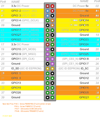
The best way to check HAT / stackable board compatibility is to map out what every pin is being used for.


The image above illustrates the pin usage for the robot. The key is as follows:

  • Orange Pins - Are general I/O pins used for the PTZ servo's and ultrasonic sensor.
  • Blue Pins - Motor Driver Board pin usage.
  • Yellow Pins - Pi Top PULSE HAT pin usage.
Thus we don't have any electrical conflicts and can move on to the mechanical interfacing issues.


To call something a HAT it must meet the HAT requirements. We are using the Seeed Motor Driver Board (shown above) which can't be called a HAT because it doesn't have a full size 40W GPIO connector or an ID EEPROM. This presents us with two problems:

  1. We need access to 6 of the 14 pins which are not extended through the Motor Board.
  2. Even if all 40 pins were extended, placing the PULSE on top of the Motor Board wouldn't allow access to the power and GPIO pins used for the servo PTZ control and ultrasonic sensor. 
To solve this issue, we need a GPIO expansion shield which provides 3 x 40 pin connections in parallel. We can then use a couple of male to female cables to connect our "HAT's". We will conclude this build in the next post (once the expansion shield has arrived).


Thursday, September 14, 2017

Flight Tracking (ADS-B) using the Raspberry Pi


In a previous post we looked at getting ADS-B tracking working on a pcDuino, to compare build difficulty with a Raspberry Pi, we built one of those as well. TL;DR version - it is much easier and you get the latest version of PiAware.

To get Dump1090 and PiAware working on a Raspberry Pi the easiest way is to just download a version of Raspbian with the software preloaded and then copy it to a SD card. Done. Full instructions are available on the FlightAware website.

We made things a bit harder for ourselves because we wanted to also try out the 4D Systems 2.4" touchscreen HAT. This requires its own drivers.

4DPi 24 HAT Display


The 4DPi-24-HAT is a 2.4" 320x240 Primary Display HAT for the Raspberry Pi, which plugs directly on top of a Raspberry Pi. It features an integrated Resistive Touch panel, enabling the 4DPi-24-HAT to function with the Raspberry Pi without the need for a mouse (theoretically). In practise the touch part of the screen is unusable. You will need a mouse to do anything useful.

Communication between the 4DPi-24-HAT and the Raspberry Pi is via the high speed 48Mhz SPI connection.

The HAT also features 5 push buttons, and a backlight. Supposedly this backlight can be configured as either On/Off or PWM controlled, selectable by an on board jumper, but only one position worked for us - see point 2 below.

The pushbuttons can be used in a python script (for example) but it isn't totally straight forward. Have a look at the data sheet for some examples.


There are a few tricks to getting this display to work with the Raspberry Pi:

  1. Make sure you download the latest drivers. The link in the instructions which came with my HAT was for an older version (which didn't work with the Raspberry Pi 3).
  2. Set the backlight link to ON/OFF not PWM. Mine came with PWM selected but it wouldn't work in this configuration. A definite trap for young players! It took me a while to track this down.
  3. You will need a couple of PCB stand offs. Get ones with a M2.5 thread and the body should be 11mm in length. These are not provided (but should be).

Optimising the Display


The 4DPi-24-HAT has a 320x240 resolution, so expectations need to be realistic about what can be usefully displayed. 

Raspbian has not been optimised to run on a display with this resolution, so there are some menus and applications which will not display correctly, or fit on the screen.

This can be helped somewhat, by setting up the display appearances, and setting fonts and
menus to be smaller. You will need to use a USB mouse and keyboard to perform this set up.

Raspberry Menu -> Preferences -> Appearance
Settings
go to Menu Bar tab
Select Small

go to System tab
click on font (Robo Light)
drag window, to see font size, select 8
(close window [x])

Click on File Manager in Menu Bar
Go to Edit, select Preferences
Select Display
Choose smallest icon sizes for all icon types
Click on "Size of Large Icons", press tab 6 times (as
the OK button is not visible), Press enter

Right click on menu bar (just left from pi menu,
near bottom edge of menu bar), to get a pop-up
menu.

Choose Add/Remove Panel Items
Remove unwanted items (eg Bluetooth)
(close window [x])

Raspberry Menu->Shutdown->Reboot

Installing Dump1090 and PiAware


To install Dump1090 and PiAware on an exisiting Raspbian installation, follow these instructions on FlightAware. It is very straight forward. The best way is to ssh in and paste the commands into terminal. Once you have plugged the USB SDR in and rebooted you should be up and running. 

We used the same USB DVB-T TV Tuner RTL2832U + R820T as our SDR. You can get these very cheaply on E-Bay.


Notice in the screen shot below that we are running the latest version of PiAware (unlike the older version we were using on the pcDuino).


Auto Load PiAware on Boot


We wanted the Raspberry Pi to auto load the PiAware web site for our ADS-B station every time the system is rebooted. To do this, first make a copy of the LXDE autostart file:

$ cp /etc/xdg/lxsession/LXDE-pi/autostart /home/pi/.config/lxsession/LXDE-pi/autostart
Then edit it:

sudo nano /home/pi/.config/lxsession/LXDE-pi/autostart
And add the following:

@xscreensaver -no-splash 
@xset s off
@xset -dpms
@xset s noblank
@chromium-browser --incognito --kiosk http://localhost:8080
Save the file, reboot and you should be good.

Comparison with pcDuino


As expected it is a lot easier (trivial in fact) to get PiAware to work on the Raspberry Pi than the pcDuino. The biggest issues we had were with the 4D Systems 2.4" Display HAT - which I don't think add much value in this instance.