Step 1: Construct the Power Distribution Board
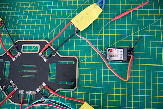
The F450 airframe includes a power distribution board. The first thing that we need to do is to tin the connections for the Electronic Speed Controllers (ESC's) and the LiPo battery.
Pre-tin the ESC power leads (red and black) as well. This will make soldering them together much easier.
Unless you have asbestos fingers you will need a pair of long nose pliers to hold the wires in place. Make sure that you wire the ESC's the right way round, the red wires go to the positive (+) pad and the black to ground (-).
In a later part of this tutorial you will read about why I burnt out and needed to replace a couple of the ESC's. If you have bought the cheap versions like I did, you may want to install bullet plugs on the power connections as well as the motor connections. This may save some re-soldering.
Wire up the Deans T style plug, this will allow you to easily disconnect/replace the LiPo battery when required. I found the T plug/sockets on eBay. Have a look at the photos below.
I am also taking the power for the top platform (for the Arduino) from the battery plug. Solder the plug connections first, then solder the short wires to the two pads on the distribution board. Double check the polarity before soldering. Make sure you put the heat-shrink on the plug wires before you solder the other end!
If I did this again, I would add a power switch on the positive lead to the battery. It can be tricky pulling apart the T plug when the props are spinning.
Once you have soldered all of the connections to the Power Distribution Board you can check continuity using a multimeter. Check that all the grounds are connected and that all the positive terminals are connected.
Step 2: Flysky FS T6 Transmitter and FS R6B Receiver Binding Procedure
The binding procedure between the FlySky Transmitter and Receiver is fairly straight forward. It is easiest to do this before you connect any more wires. You need the Power Distribution Board complete so that you can power the ESC from the LiPo. Make sure you charge your LiPo before starting.
You will need the transmitter, the receiver, the link cable / binding plug (comes with the receiver), and one ESC.
Your ESC control cables may come in various colours. You can use the table below to decode which is which. The ESC may or may not come with a battery eliminator circuit (BEC). If yours does, there should be 5VDC on the positive (red) lead, relative to ground, when the LiPo is connected. We wont be using the BEC, all control power will come from the Arduino 5V bus.
- Put the bind plug (which is just a jumper wire) into the battery connector at the top of the R6B receiver.

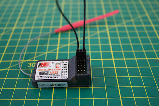
- Plug the ESC servo/control cable into channel 3 (CH3 - throttle channel) of the receiver. The signal cable (orange on my ESC) should be next to the CH3 writing on the receiver. Ground (brown or black) should be to the far right (refer to photo). You can actually plug into any of the channels, but 3 is traditional!

- Make sure that none of the cables are touching each other, then connect the LiPo to the Power Distribution Board via the Dean T plug.
- The LED on the side of the receiver should start blinking. This indicates that it is ready to bind to a transmitter.
- Press and HOLD the bind key on the back of the transmitter. Turn on the transmitter, wait 3 seconds or so and then release the bind key when the LED on the receiver stops blinking. The LED on the receiver should now be solid on.
- Disconnect the battery from the Power Distribution Board. Remove the bind plug from the receiver, and turn off the transmitter.
- To check that binding is in place, turn on the transmitter, reconnect the LiPo to the Power Distribution Board and the receiver LED should be solid on indicating a connection. Turn off the Transmitter and the receiver LED will go out. Done! Disconnect the battery, and we can resume construction.
Step 3: MPU 6050 Gyros / Accelerometer
Next we need to connect some wires to the MPU-6050. Use the light duty hook up wire and solder to the Vcc (red), GND (black), SCL (white) and SDA (blue) pads on the MPU-6050. You can use whatever colour wire you want but keep track of what is what.
We now come to the first challenge. The clone version of the F450 airframe has a large hole in the top platform, right where we want to mount the MPU-6050! To provide accurate roll, yaw and pitch information, the MPU-6050 needs to be mounted as close to the centre of the Drone as possible.
The F450 Top Platform - with large hole in the middle!
In the original F450, the battery is mounted on the top platform and the flight controller is mounted on the Power Distribution Board. We are going to do it the other way around, with the battery at the bottom (lower centre of gravity) and the electronics on top (better access).
We will also mount the FS R6B receiver on this platform. It is about 45mm long and sticks out over the original top platform.
To solve both of these issues, we designed and 3D printed a light mounting bracket to cover up the top platform holes and make the MPU-6050 and R6B easy to mount using double sided tape. We used SketchUp to design the bracket. It is 125 mm long, 32 mm wide, and the rectangular portion is 1 mm deep. You can download a copy of the F450 Bracket STL File from Thingiverse.
The cylinder diameter is 28 mm and another 1.5 mm deep on top of the rectangle. This fills the hole in the top platform. It is a firm fit so you may need to adjust this based on your 3D printer tolerance.
Once you have created the part (or downloaded mine), you will need a slicer like Cura to produce the gcode file for your 3D printer.
The orientation of the gyro is not important as long as the Z-axis is vertical (perpendicular to the surface) and the edges of the gyro are aligned with the edges of the quadcopter. The setup software will detect the gyro's orientation and invert the gyro and accelerometer axis if necessary.
Mount the gyro with thin double side tape as close to the centre of the top platform as possible. Don't use foam tape or other dampening material as this could decrease accuracy. I found that tweezers made removal of the tape backing paper easier. While the software doesn't care which way the gyro is mounted, from a construction point of view, I had the wires closest to the back of the platform.
You can then mount the receiver behind the MPU-6050, also using double sided tape. I also located the receiver channel connections at the back of the platform for ease of access.
Step 4: Mount the Arduino
The next challenge is mounting the Arduino. You could drill some holes in the top platform and use spacers to mount, but we like using our 3D printer so we designed a purpose built mounting bracket.
The four mounting holes in the centre of the bracket match the holes in the centre of the F450 top bracket. You can download a copy of the Arduino bracket from Thingiverse.
The 4 x 15mm nylon tapped spacers used to attach the Arduino mounting bracket have the added benefit of holding the gyro and receiver bracket in place.
The bracket can be mounted in any orientation, but we located it so that the Arduino digital inputs were towards the back of the drone. The receiver channel connections, MPU-6050 SDA and SCL connections are all wired to that side of the Arduino. This also places the wired status LED at the back of the drone where it should be most visible, assuming the drone spends most of its time flying away from you!
In part 3 we will complete the hardware build.


No comments:
Post a Comment